


48
SERVICE (Cont.)
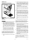
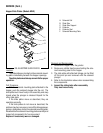
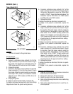
Location:
The timer is located on the timer bracket in the
grinder base. The bracket can be removed by loosening
the two 8-32 screws beneath the timer dial(s).
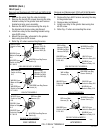
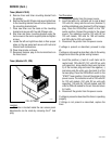
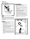
Test Procedure:
1. Disconnect the grinder from the power supply.
2. Check the voltage across terminals TL1 & TL2 with
a voltmeter when the “Off/On/Start switch is placed
in the “START” (right) position and released. Con-
nect grinder to the power supply. The indication
must be:
(a) 120 volts ac for two wire 120 volt models.
(b) 240 volts ac for two wire 240 volt models.
3. Disconnect the grinder from the power supply.
If voltage is present as described, proceed to step 4.
If voltage is not present as described, refer to the Wiring
Diagram and check the grinder wiring harness.
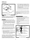
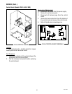
4. Remove the white/orange and white/yellow wires
from terminals TL3 & TL5.
5. Check for continuity across the white/orange and
white/yellow wires when the Off/On/Start switch
is placed in the “START” (right) position.
If continuity is present as described, reconnect the
white/orange wire to terminal TL3 and the white/yellow
wire to terminal TL5, and proceed to step 6.
If continuity is not present as described, refer to the Wir-
ing Diagram and check the grinder wiring harness.
6. Check the voltage across terminals TL1 and TL4
with a voltmeter when the Off/On/Start switch
is placed in the “START” (right) position and
released. Connect grinder to the power supply.
The indication must be:
(a) 120 volts ac for two wire 120 volt models.
(b) 240 volts ac for two wire 240 volt models.
7. Disconnect the grinder from the power supply.
If voltage is present as described, the timer is operating
properly. Refer to the Adjustments section to vary the
amount dispensed.
If voltage is not present as described, replace the
timer.
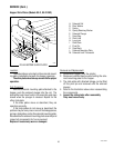
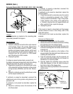
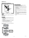
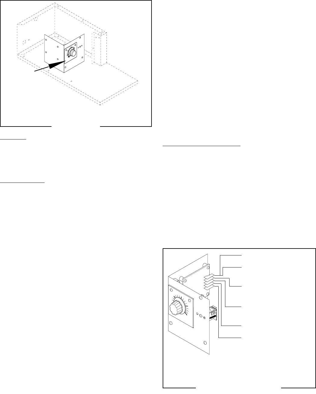
Removal and Replacement:
1. Remove all wires from the timer terminals.
2. Remove the four 6-32 screws and nuts holding the
circuit board to the timer bracket.
3. Remove the two 6-32 screws and nuts holding the
dial plate to the timer bracket.
4. Install the new dial plate and circuit board to the
timer bracket.
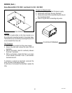
5. Refer to the illustration below when reconnecting
the wires.
6. Refer to the Adjustments section to vary the amount
dispensed.
MINUTES
BUNN-O-MATIC
P/N 2620- 12
0 VAC
MINUTES
BUNN-O-MATIC
P/N
2620-
120
VAC
MINUTES
BUNN-O-MATIC
P/N 2620- 120 VAC
2
3
4
5
WHI/RED to Relay N.O.
WHI/RED to
Off/On/Start Switch
WHI to Cordset (120 v)
RED/BLK to Cordset (240 v)
WHI/ORA to
Off/On/Start Switch
WHI/GRN to Relay Coil
WHI/YEL to
Off/On/Start Switch
P1312
P1313
Single set timer shown
Multi set timer (Urn/Carafe) connections are the same
Single set timer shown
Multi set timer (Urn/Carafe) similar
Timer (Model G9)
FIG 50 TIMER
FIG 51 TIMER TERMINALS
41545 122209