


56
SERVICE (Cont.)
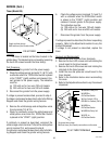
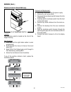
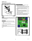
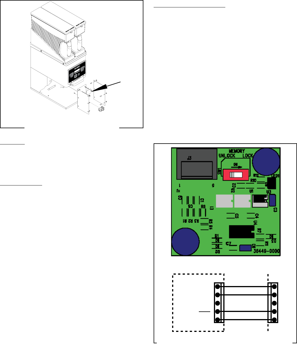
Memory Clock Board (Model MHG)
Location:
The memory clock board is located on the component
mounting bracket mounted to the grinder base inside
the front access panel.
Test Procedure:
1. Disconnect the grinder from the power supply.
2. Disconnect the wiring harness on the memory
board.
3. Check for 5VDC on J1-4 and J1-5.
If voltage is not present as described the memory board
is operating properly.
If voltage is present as described, replace the memory
board.
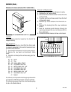
FIG 64 MEMORY CLOCK BOARD
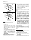
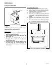
Removal and Replacement
1. Disconnect the grinder from the power supply.
2. Remove the front access panel.
3. Remove the two 8-32 screws securing the compo-
nent bracket to the grinder base and tilt forward to
gain access to the memory clock board.
5. Disconnect the harness from the memory clock
board.
6. Remove the two 6-32 nuts attaching the memory
clock board to the component bracket.
7. Remove the two spacers from the old board and
attach to the new board.
8. Install new memory board using two #6-32 nuts
to secure board to the component bracket.
9. Refer to Fig. 65 when reconnecting the wires.
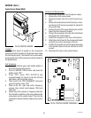
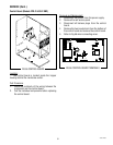
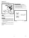
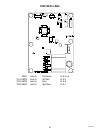
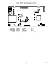
FIG. 65 MEMORY CLOCK BOARD CONNECTORS
MEMORY
BOARD
GRN
WHI
RED
BLK
+5VDC
J1-1
J1-5
J16-1
J16-5
41545 122209