


26
SERVICE (Cont.)
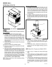
2. The entire wiring harness must be fed into the bottom
of the grinder housing through the hole in the motor
mounting plate.
3. Remove both 6-32 screws beneath the upper front
inspection panel.
4. Remove the six 10-32, hex head screws on top of the
motor mounting plate.
5. Slowly slide the assembly out the rear of the grinder
housing. The mounting plate will have to be raised
to gain clearance for the motor hardware and wiring
harness bushing.
6. Remove the four 5/16”-18 bolts and nuts to separate
the motor from the mounting plate.
7. Mount the new motor and tighten the four bolts and
nuts. They should be tightened approximately one full
turn past snug.
8. Slide the motor mounting plate into the rear of the
grinder housing.
9. Feed the wiring harness into the top of the housing
through the hole in the motor plate.
10. Reinstall the six 10-32 hex head screws through the
motor plate and the two 6-32 screws through the
housing.
11. Reattach the green wire to the 10-32 stud on the motor
mounting plate.
12. Refer to the Off/On/Start switch section when recon-
necting the switch wires.
13. Refer to the illustration below when reconnecting the
motor wires.
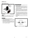
P1309
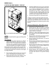
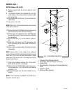
Location:
The motor is located in the upper wrapper under the
hopper.
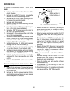
Test Procedure:
1. Remove the hole plug located on the right side of the
housing. Press the red “Reset” button visible through
the opening. Listen carefully for a “click”. This resets
the motor protection circuit and may indicate that
something other than coffee was inserted into the
hopper for grinding.
If the grinder remains unable to start, proceed to step 2.
If the grinder stops operating shortly after starting, refer to
the removal and replacement steps to gain access-to the
grind chamber. Remove any foreign materials that may be
found.
2. Disconnect the grinder from the power supply.
3. Remove the electrical access panel at the rear of the
motor.
4. Check the voltage across terminals L1 & L2 of the
motor with a voltmeter when the Off/On/Start switch
is placed in the “START” (right) position and released.
Connect the grinder to the power supply. The indication
must be:
(a) 120 volts ac for two wire 120 volt models.
(b) 240 volts ac for two wire 240 volt models.
5. Disconnect the grinder from the power supply.
If voltage is present as described and the grinder remains
unable to start, replace the motor.
If voltage is not present as described, refer to the Wiring
Diagrams, and check the grinder wiring harness.
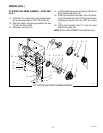
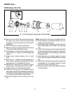
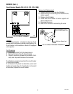
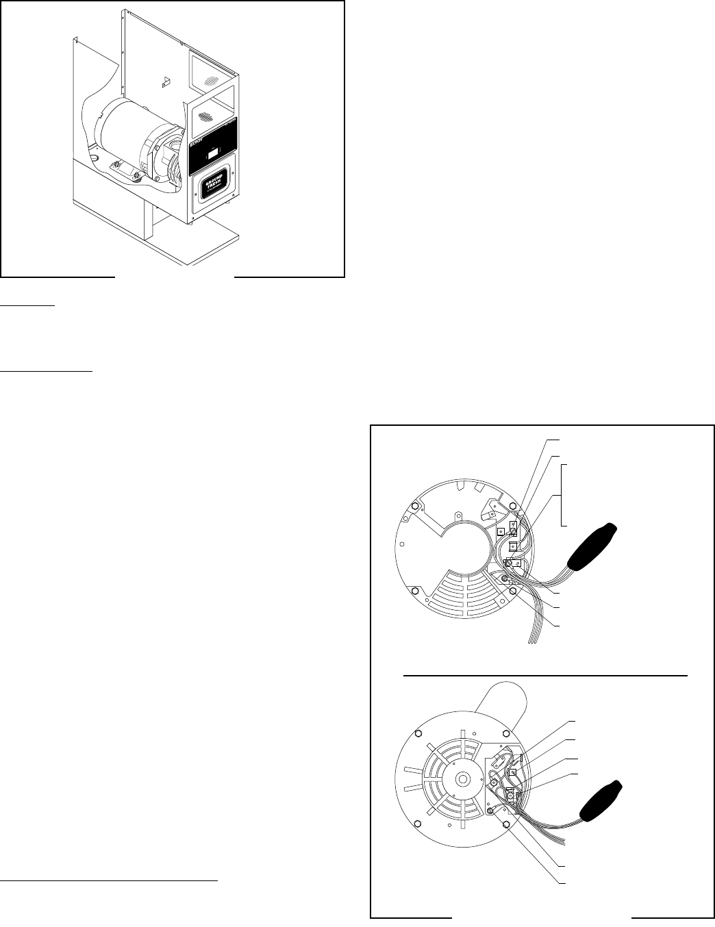
Removal and Replacement - MOTOR
1. Remove all wires from the Off/On/Start switch, motor,
and motor mounting plate.
GRN to Chasis Ground
YEL to Snubber
P621
WHI/ BLU to Snubber
WHI/BLU to Relay
WHI/BLK to Snubber
WHI/BLK to Cordset
(120V models)
RED/BLK to Cordset
(230V models)
FRANKLIN MOTOR
MARATHON MOTOR
GRN to Chasis Ground
YEL to Snubber
WHI/ BLU to Snubber
WHI/BLK to Snubber
WHI/BLU to Relay
WHI/BLK to Cordset
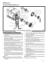
MOTOR (Models G9, G9-2, MHG)
FIG. 15 MOTOR
FIG. 16 MOTOR WIRING
41545 122209