


49
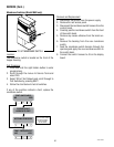
SERVICE (Cont.)
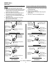
D
IS
PE
N
S
E
TIM
E
(
S
e
c
o
n
d
s
)
D
IS
P
L
AY
In
c
r
e
a
s
e
D
e
c
r
e
a
s
e
Rea
do
ut
w
i
ll be
d
i
splayed
for 5 m
i
nutes
.
T
im
er can
only be
adj
us
ted
w
hi
le
readout
i
s displa
ye
d
.
+
WARN ING
HAZARDOUS VOLTAGE
U
N
P
LU
G
G
R
I
N
D
E
R
BE
F
OR
E
R
E
M
O
V
I
N
G
R
I
G
H
T
DI
S
PENS
E
T
IME
(S
E
CO
ND
S
)
3.
2
6
1
0
15
2
0
25
30
32
3.2
.
4.4
1
1
2
2
3
3
4
6
1
0
15
2
0
2
5
30
32
4
LEF
T
H
IG
H
U
NPLU
G
G
R
I
N
D
E
R
B
EF
O
R
E
R
E
M
O
V
IN
G
WARN ING
HAZ
ARDOUS
VOLTAGE
H
I
G
H
L
O
W
H
I
G
H
H
I
G
H
L
O
W
LO
W
LO
W
O
N
O
F
F
O
N
OFF
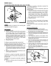
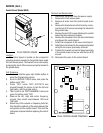
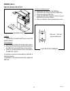
Location:
The timer is located in the grinder base.
Test Procedure:
1. Unplug the grinder.
2. Connect a voltmeter across contacts 1 & 2 of the
larger connector (P4) on the timer board. Plug-in
the grinder. The indication must be 120 volts ac for
120V models and 230 volts ac for 230V models.
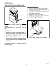
3. Unplug the grinder.
4. Connect a voltmeter across contacts 2 & 6 of the
larger connector (P4) on the timer board. Plug-in
the grinder. When the control switch is in any posi-
tion except “OFF” (center), the indication must be
120 volts ac for 120V models and 230 volts ac for
230V models.
5. Unplug the grinder.
If voltage is present as described, proceed to #6.
If voltage is not present as described, refer to the Wiring
Diagram and check the grinder wiring harness.
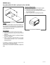
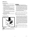
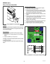
P613
Digital Timer
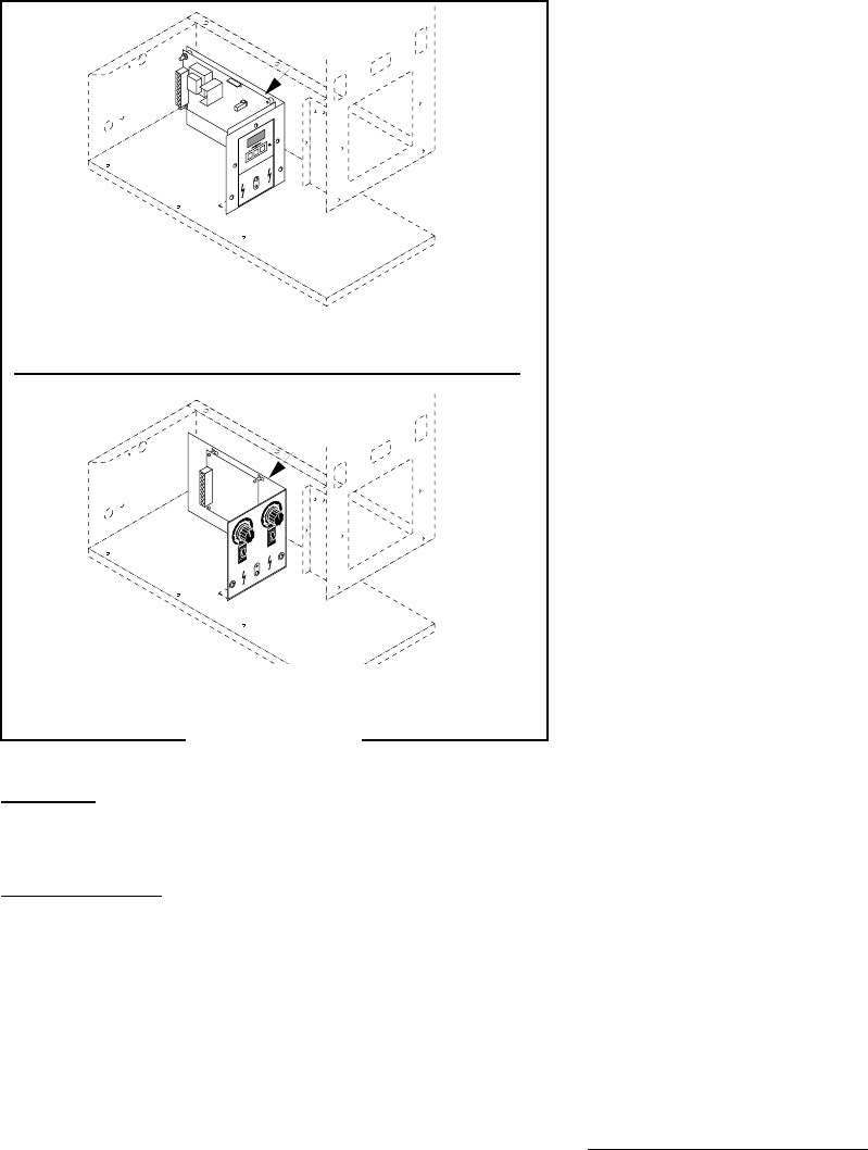
Analog Timer
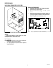
6. Connect a voltmeter across contacts 3 & 7 of the
larger connector (P4) on the timer board. Plug-in
the grinder. Momentarily press the Off/On/Start
switch to “START” (lower) position and release. The
indication must be 120 volts ac for 120V models
and 230 volts ac for 230V models.
7. Unplug the grinder.
If voltage is present as described, proceed to #8.
If voltage is not present as described, replace the
timer.
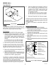
8. Connect a voltmeter across contacts 4 & 7 of the
larger connector (P4) on the timer board. Plug-in
the grinder. Place the hopper selector switch to
the left position. Momentarily press the Off/On/
Start switch to the “START” (lower) position and
release. The indication must be 120 volts ac for
120V models and 230 volts ac for 230V models and
should remain for the approximate timer setting.
9. Unplug the grinder.
If voltage is present as described, proceed to #10.
If voltage is not present as described, replace the
timer.
10. Connect a voltmeter across contacts 5 & 7 of the
larger connector (P4) on the timer board. Plug-in
the grinder. Place the hopper selector switch to
the right position. Momentarily press the Off/On/
Start switch to the “START” (lower) position and
release. The indication must be 120 volts ac for
120V models and 230 volts ac for 230V models and
should remain for the approximate timer setting.
11. Unplug the grinder.
If voltage is present as described, the timer is operat-
ing properly.
If voltage is not present as described, replace the
timer.
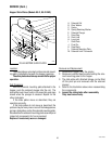
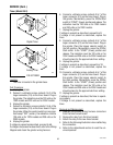
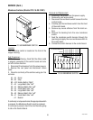
Removal and Replacement:
1. Separate the grinder wiring harness connectors
from the timer circuit board.
2. Remove the relay from the timer bracket.
3. Attach the relay to the new timer bracket.
4. Refer to the following illustration when reattaching
the connectors.
5. Refer to the Adjustments section to reset the vol-
ume dispensed.
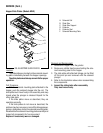
Timer (Model G9-2)
FIG 52 TIMER
41545 122209