45
SERVICE (Cont.)
Left
Right
WHI/ORN to
Timer P4-4
RED/BLK to
Right Solenoid
RED/BLK to
Timer P4-7
WHI/YEL to
Timer P4-5
RED/BLK to
Left Solenoid
P612
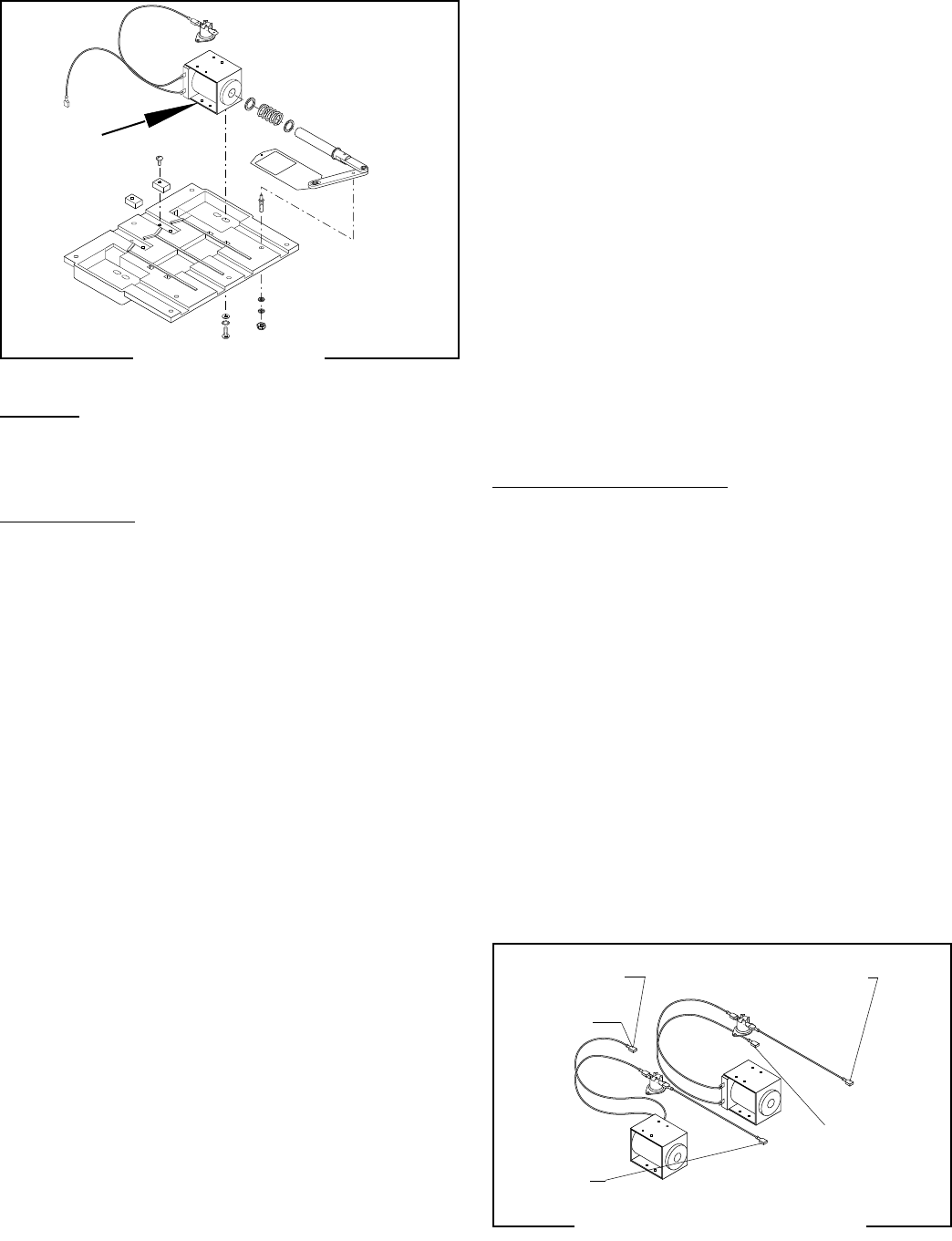
Location:
The solenoids are located on the mounting plate
immediately beneath the hoppers.
Test Procedure:
1. Unplug the grinder.
2. Connect a voltmeter across the left or right solenoid
coil terminals. Plug-in the grinder. Momentarily
press the Off/On/Start switch to “START” (lower)
position and release (hopper selector switch must
be corresponding to the suspect solenoid). The
indication must be 120 volts ac for 120V models
and 230 volts ac for 230V models.
3. Unplug the grinder.
If voltage is present as described, proceed to #4.
If voltage is not present as described, refer to the Wiring
Diagram and check the grinder wiring harness.
4. Separate the connectors on the white/brown wires
of the solenoids from the connectors on the grinder
wiring harness (RED/BLK) and the limit thermo-
stat.
5. Check for continuity across the white/brown wires
on the suspect solenoid coil.
If continuity is present as described, reconnect the
white/brown wires to the grinder wiring harness, and
proceed to #6.
If continuity is not present as described, replace the
solenoid.
6. Check for continuity across the terminals of the
limit thermostat.
P608
If continuity is present as described, reconnect the
wires, and proceed to #7.
If continuity is not present as described, replace the
limit thermostat.
7. Check the solenoid for coil action when the control
switch is momentarily pressed to the “START”
(lower) position and released. Plug-in the grinder.
Listen carefully in the vicinity of the solenoid for
a “clicking” sound as the coil magnet attracts and
after a period of time, repels the plunger.
8. Unplug the grinder.
If the sound is heard as described and the plunger
remains unable to move or move freely, refer to the
slide plate section.
If the sound is not heard as described, replace the
solenoid.
Removal and Replacement:
1. Remove the hopper assy from the grinder.
2. Remove the four 8-32 slotted-head screws holding
the solenoid coil to the solenoid panel.
3. Feed the white/brown wires through the hole in the
solenoid mounting plate and loosely install the new
solenoid coil.
4. Look through the collector on the bottom of the
assy and adjust the slide plate travel distance when
installing the solenoid coil.
5. Push the solenoid plunger into the solenoid coil
with your hand while moving the coil forward or
backward in its mounting holes.
6. Securely tighten the mounting screws when the
slide plate appears to have no metal showing in
the front or back of the hopper hole.
7. Refer to the following illustration when reconnect-
ing the wires.
Solenoids (Models MHG, FPG-2 DBC, LPG-2, G9-2, G9-2 DBC)
FIG 46 SOLENOIDS
FIG 47 SOLENOID TERMINALS
41545 122209


