


47
SERVICE (Cont.)
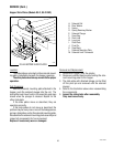
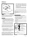
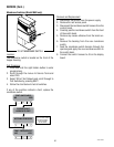
Timer (Model LPG-2E)
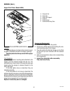
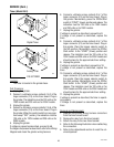
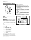
Timer (Models LPG, FPG)
P1748
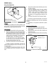
FIG. 49 TIMER
Location:
The timer is located inside the rear access panel.
Adjustments can be made by removing the 2” hole
plug.
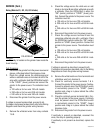
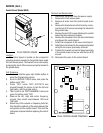
Test Procedure:
1. Disconnect grinder from the power source.
2. Insert the leads of a voltmeter set to read at least
120 volts AC, along side the red wire (terminal 1)
and the white/black wire (terminal 2) of the harness
plug. Place the Off/On/Start switch in the “ON”
center position. Connect the grinder to the power
source. The indication must be 120 volts AC for
120 volt models, 100 volts for 100 volt models,
and 230 volts for 230 volt models.
3. Disconnect the grinder from the power source.
If voltage is present as described, proceed to step
#4.
If voltage is not present as described, refer to the wiring
diagram and check the grinder wiring harness.
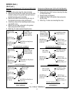
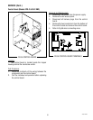
4. Insert the positive (+) lead of a volt meter set to
read at least 120 volts DC (157 volts DC on units
with capacitor), along side the black wire (terminal
3) of the harness plug and insert the negative (-)
lead along side the white wire (terminal 6) of the
harness plug. Place the Off/On/Start switch in the
“START” lower position. Connect the grinder to the
power source. The indication must be 120 volts DC
for 120 volt models (157 volts DC on units with
capacitor), 100 volts for 100 volt models, and 230
volts for 230 volt models for the set time and return
to 0 volts.
5. Disconnect the grinder from the power source.
If voltage is present as described the timer is operating
properly.
If Voltage is not present as described, replace the
timer.
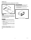
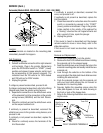
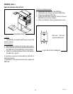
5. Remove timer and timer mounting bracket from
the grinder.
6. Remove the four #6-32 keps nuts securing the timer
to the mounting bracket. Leave the four spacers on
the mounting bracket studs.
7. Place new timer over the studs on the mounting
bracket and secure with four #6-32 keps nuts.
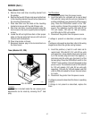
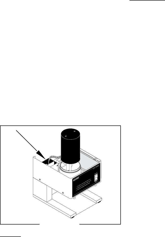
8. Slip timer and timer mounting bracket under the
two screws on the motor support plate and tighten
screws.
9. Locate the left and right timer dials in their proper
place on the rear panel and secure with nuts and
internal tooth lockwashers.
10. Place timer knobs on timers.
11. Reconnect harness plug to the terminal block on
the timer board.
41545 122209