


37
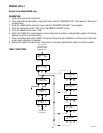
SMALL MEDIUM LARGE
P2946
SERVICE (Cont.)
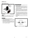
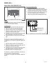
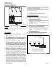
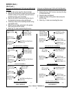
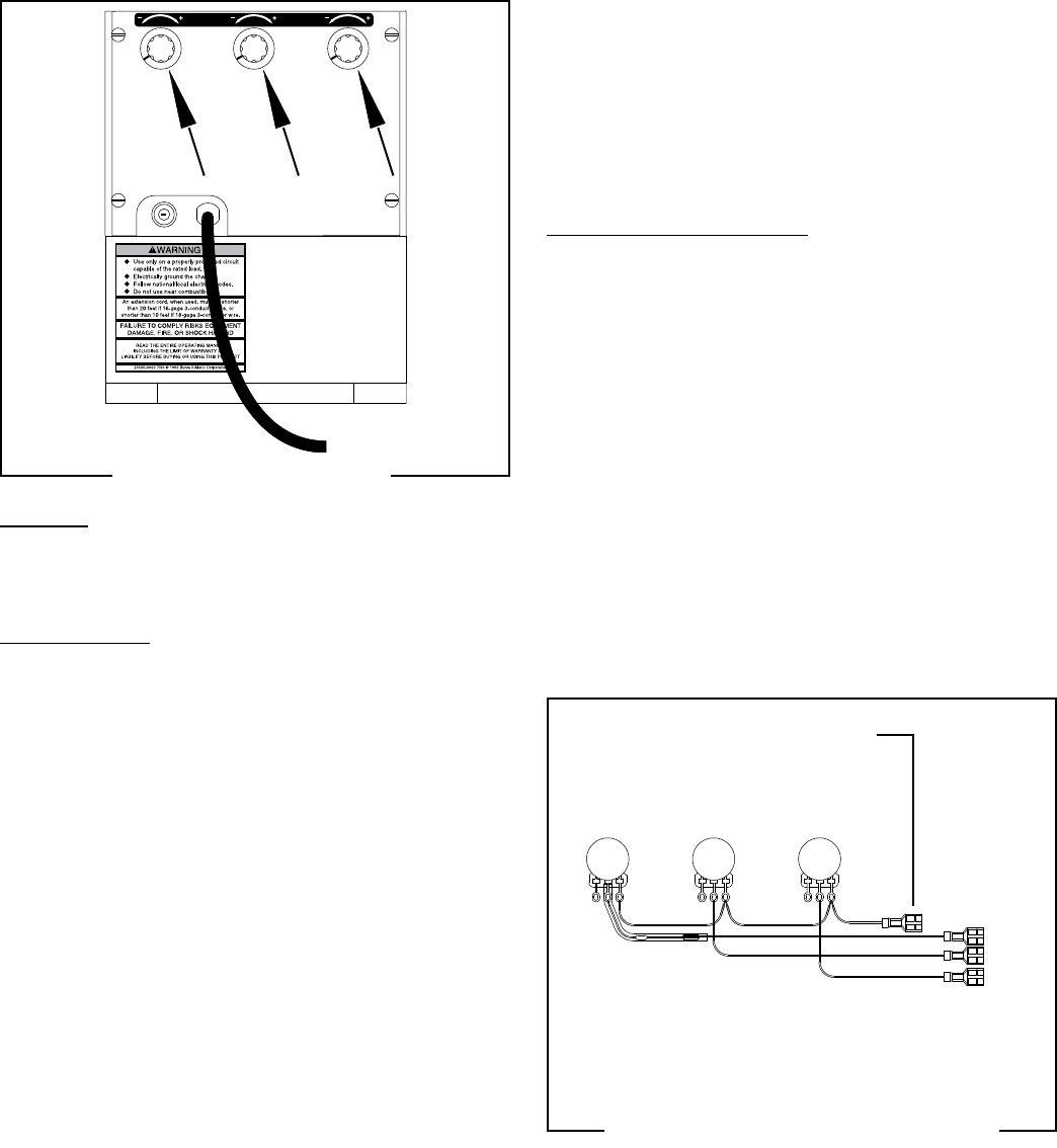
FIG 34 POTENTIOMETERS
Location:
The potentiometer switches are located on the top
rear of the hopper housing.
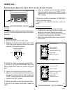
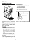
Test Procedure:
1. Disconnect the grinder from the power source.
2. Open hopper lid and loosen four screws inside the
hopper and remove hopper.
3. Disconnect the BRN wire from the control board.
4. Disconnect the PNK, GRY, and TAN wires from the
front selector switch.
5. Connect an ohmmeter to the BRN wire. Connect
the other lead from the meter to the TAN wire.
Turn the knob for the SMALL potentiometer all the
way counterclockwise. The meter should read <3K
ohm. Turn the knob all the way clockwise, the meter
should read between 94K and 116K ohms.
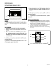
6. Connect an ohmmeter to the GRY wire. Connect
the other lead from the meter to the TAN wire.
Turn the knob for the MEDIUM potentiometer all
the way counterclockwise. The meter should read
<3K ohm. Turn the knob all the way clockwise, the
meter should read between 94K and 116K ohms.
7. Connect an ohmmeter to the TAN wire. Connect
the other lead from the meter to the TAN wire. Turn
the knob for the LARGE potentiometer all the way
counterclockwise. The meter should read between
13.5K and 19.5K ohms. Turn the knob all the way
clockwise, the meter should read between 108K
and 132K ohms.
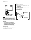
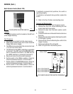
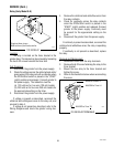
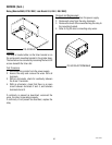
FIG 35 POTENTIOMETER TERMINALS
Potentiometer (Model FPG)
BRN to BRN WIRE
at TIMER
PNK to BATCH SELECTOR SWITCH
GRY to BATCH SELECTOR SWITCH
TAN to BATCH SELECTOR SWITCH
If continuity is present at all positions, the potentiometer
switches are operating properly.
If continuity is not present at any position, replace the
potentiometer switches.
8. Refer to Fig 35 when reconnecting wires.
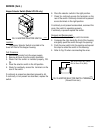
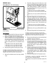
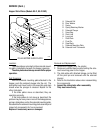
Removal and Replacement:
1. Disconnect the grinder from the power source.
2. Remove the four 8-32 screws attaching the rear
access panel and move aside.
3. Disconnect three wires to the batch selector switch
and the one wire to the timer.
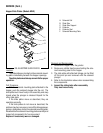
4. Loosen the setscrews on the switch knobs and
remove the knobs.
5. Remove the three nuts and lockwashers attaching
the switches to the rear access panel.
6. Inspect and replace the adhesive backed sponge
washers on the rear access panel if necessary.
7. Install the new potentiometer switches and tighten
the lockwashers and nuts.
8. Replace the knobs and tighten the setscrews.
9.Refer to Fig. 35 when reconnecting wires.
41545 122209