


40
SERVICE (Cont.)
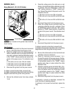
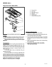
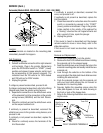
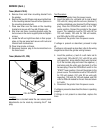
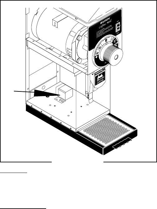
Location:
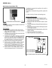
The relay is located on the grinder base inside the
lower housing.
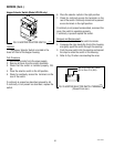
Test Procedure:
1. Disconnect the grinder from the power source and
place a coffee bag behind the dispense chute.
2. Check the voltage across the white/orange and
white or red/black wires on terminals A & B of the
relay with a voltmeter. Hold the Off/On/Start switch
in the “START” (lower) position and connect the
grinder to the power source. The indication must
be:
a. 120 volts ac for two wire 120 volt models.
b. 230 volts ac for two wire 230 volt models.
c. 240 volts ac for two wire 240 volt models
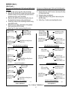
3. Disconnect the grinder from the power source.
If voltage is present as described, proceed to #4.
If voltage is not present as described, refer to the Wiring
Diagrams and check the grinder wiring harness.
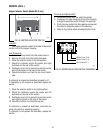
4. Remove the white/red wires from relay contacts
7 & 9.
5. Check the voltage across the white wire or red/
black on terminal B and either white/red wire with
a voltmeter. Place the Off/On/Start in either the
“ON” (center) position or “START” (lower) posi-
tion. Connect the grinder to the power source. The
indication must be:
a. 120 volts ac for two wire 120 volt models.
b. 230 volts ac for two wire 230 volt 50 Hz mod-
els.
c. 240 volts ac for two wire 240 volt 60 Hz mod-
els.
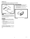
6. Disconnect the grinder from the power source.
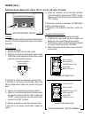
7. Check the voltage across terminal B and the
remaining white/red wire with a voltmeter. Place
the Off/On/Start switch in either the “ON” (center)
position or “START (lower) position. Connect the
grinder to the power source. The indication must
be:
a. 120 volts ac for two wire 120 volt models.
b. 230 volts ac for two wire 230 volt 50 Hz mod-
els.
c. 240 volts ac for two wire 240 volt 60 Hz mod-
els.
8. Disconnect the grinder from the power source.
If voltage is present as described, proceed to #9.
If voltage is not present as described, refer to the Wiring
Diagrams and check the grinder wiring harness.
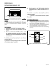
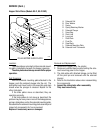
9. Remove the white/violet wire from terminal 6 and
white/blue wire from terminal 4.
10. Check for continuity across terminals 7 & 4.
Connect the grinder to the power source. Continu-
itymust be present when the Off/On/Start switch
is momentarily placed in the “START” (lower)
position and a bag is in place behind the coffee
dispense chute.
11. Check for continuity across terminals 9 & 6. Con-
nect the grinder to the power source. Continuity
must be present when the Off/On/Start switch
is momentarily placed in the “START” (lower)
position and a bag is in place behind the coffee
dispense chute.
12. Disconnect the grinder from the power source.
If continuity is present as described, reconnect the
wires, the relay is operating properly.
If continuity is not present as described, replace the
relay.
Relay (Models G1, G2, G3, G2 trifecta)
FIG.40 RELAY
P1704
41545 072710