


20
SERVICE (Cont.)
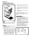
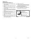
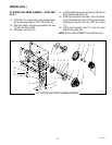
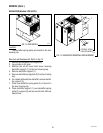
DC MOTOR AND GRIND CHAMBER - G1MD ONLY
(cont.)
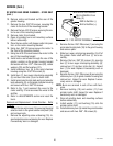
BLU to BLU from Rectifier
BLU to WHI/BLU from
Relay (3)
RED to Rectifier (-)
BLK to Rectifier (+)
FIG. 7 DC MOTOR TERMINALS
P1710
10. Remove motor and bracket out the rear of the
grinder housing.
11. Remove the two .250”-20 screws securing the
motor to the front of the mounting bracket.
12. Remove the two #10-32 screws securing the mo-
tor to rear of the mounting bracket.
13 Remove motor from bracket.
14. Clean all grinding burrs and mounting surfaces
before reassembly.
15 Place the new motor with hopper collar into posi-
tion on the motor mounting bracket.
16. Using two .250”-20 screws secure the motor to
the front of the mounting bracket.
17. Using two #10-32 screws secure the motor to the
rear of the mounting bracket
18. Install motor and bracket through the rear of the
grinder, position on the grinder housing bracket
and secure with four .312”-18 screws (20), rubber
washers (22) and flat washers (21).
19. Install stationary burr (9) to the grind chamber
housing using two .250”-20 screws (8).
20. Install burr (7), burr auger rotor/spring assembly
(3) and burr rotor disc (4) on to motor shaft.
21. Install grind selector dial plate and grind selector
knob assembly (2) on the grind chamber housing
and secure with two .250”-20 screws.
22. Refer to Fig. 7 and reconnect the wires to the
motor and Fig. 37 and reconnect the wires to the
rectifier.
23. Refer to ADJUSTMENTS section and reset the
burrs.
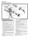
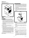
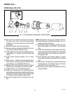
Removal and Replacement - Grind Chamber - Refer
to Fig. 8:
1. Loosen the two set screws (16) securing the grind
selector knob to the grind selector dial plate (18)
and remove knob.
2. Remove the adjusting screw w/bearing (19). In-
spect adjusting screw w/bearing for wear. Replace
if excessively worn or damaged.
3. Remove the two .250”-20 screws (1) securing the
grind selector dial plate (18) to the grind housing
and remove plate.
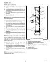
4. Slide burr auger rotor/spring assembly (3) off of
the grinder motor shaft with burr (7) as an as-
sembly.
5. Remove the two .250”-20 screws (5) securing
burr (7) to burr auger rotor/spring assembly (6),
remove burr (7) and burr rotor disc (4). Inspect
burr (7) for wear. Replace if excessively worn or
damaged.
6. Remove the two .250”-20 screws (8) securing the
stationary burr (9) to grind chamber housing and
remove burr. Inspect for wear. Replace if exces-
sively worn or damaged.
NOTE: Burrs are serviced in sets of two with hard-
ware.
7. Remove bushing (10) and washer (11) from
grinder motor shaft. Inspect for wear. Replace if
excessively worn or damaged.
8. Clean all grinding burrs and mounting surfaces
before reassembly.
9. Install washer (11) and bushing (10) onto the
grinder motor shaft.
10. Install stationary burr (9) inside the grind chamber
and secure with two .250” -20 screws (8).
41545 122209