


Page 12
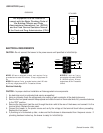
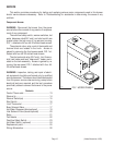
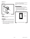
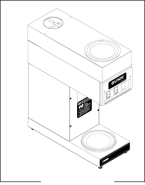
FIG. 1 ACCESS PANELS
SERVICE
This section provides procedures for testing and replacing various major components used in this brewer
should service become necessary. Refer to Troubleshooting for assistance in determining the cause of any
problem.
Component Access
WARNING - Disconnect the brewer from the power
source before the removal of any panel or the replace-
ment of any component.
The overflow safety switch, warmer switches, hot
water dispense valve(SLF only) and start switch are
located under the top cover or top warmer housing,
FIG. 1, attached with four #6-32 slotted-head screws.
The solenoid valve, relay, control thermostat and
terminal block are located in the trunk. Access is
gained by removing the front access panel, FIG. 1 at-
tached with four #8-32 slotted-head screws
The inlet solenoid valve (SLF only), limit thermo-
stat, tank heater and tank “keep warm” heater are lo-
cated on the tank assembly. Access is gained by re-
moving the rear panel, FIG. 1 attached with four #8-
32 slotted head screws.
WARNING - Inspection, testing, and repair of electri-
cal equipment should be performed only by qualified
service personnel. The brewer should be disconnected
from the power source when servicing, except when
electrical tests are required and the test procedure
specifically states to connect the brewer to the power
source.
Contents
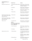
Control Thermostat...............................................13
Warmer(s) ............................................................ 14
Warmer Switch(es)...............................................15
Start Switch ..........................................................16
Limit Thermostat .................................................. 17
Brew Solenoid Valve .............................................17
Hot Water Dispense Valve(optional) .....................19
Inlet Solenoid Valve (faucet-optional) ................... 20
Relay.....................................................................21
Tank Heater...........................................................22
Overflow Safety Switch .........................................23
Hot Water Switch (optional) .................................24
Replacement parts ................................................25
Wiring Schematics............................................... 26
P1712
(Added November 1999)
1
0
0
4
3
.0
0
0
0
D
3
/9
7
©
1
9
8
8 B
U
N
N
-O
-
M
A
T
IC
C
O
R
P
O
R
A
T
I
O
N
W
H
I
B
L
U
L
IM
IT
T
H
E
R
M
O
S
T
AT
S
W
. &
T
H
ER
M
O
S
T
A
T
T
A
N
K
H
E
A
T
E
R
N
B
L
K
L
1
B
L
K
W
H
I
P
1
P
3
P
2
P
1
, P
2
, &
P
3
A
R
E P
IN
S
O
F
A
P
O
L
AR
IZ
E
D
T
H
R
E
E
-P
IN
C
O
N
N
E
C
TO
R
.
G
R
E
E
N
S
C
H
E
M
A
T
IC
W
IR
IN
G
D
IA
G
R
A
M
S
"K
E
E
P
W
A
R
M
" H
E
A
T
E
R
5
0
W
W
H
I
T
O
P
R
E
A
R
W
A
R
M
E
R
1
0
0
W
W
H
I
W
H
I
B
L
K
B
L
U
/
B
L
K
T
O
P
FR
O
N
T
W
A
R
M
E
R
1
0
0
W
W
H
I
B
L
K
B
R
N
/
B
L
K
L
O
W
E
R
W
A
R
M
E
R
1
0
0
W
W
H
I
W
H
I
B
L
K
BL
U
/B
L
K
B
R
N
/B
L
K
W
H
I
1
2
0
V
O
L
T
S
A
C
2
W
I
R
E
S
I
N
G
L
E
P
H
A
S
E
6
0
H
Z
1
4
2
5
W
W
H
I/V
IO
!
C
A
U
T
IO
N
W
A
R
M
E
R
S
A
N
D
S
U
R
F
A
C
E
S
A
R
E
H
O
T
T
O
P
F
R
O
N
T
O
N
/ L
O
W
E
R
S
T
A
R
T
T
O
P
R
E
A
R
L
O
W
E
R
T
O
P
F
R
O
N
T
T
O
P
R
E
A
R