


Page 21
SERVICE (cont.)
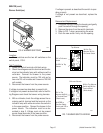
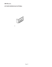
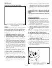
Relay
FIG. 18 RELAY
P2015
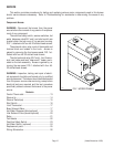
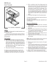
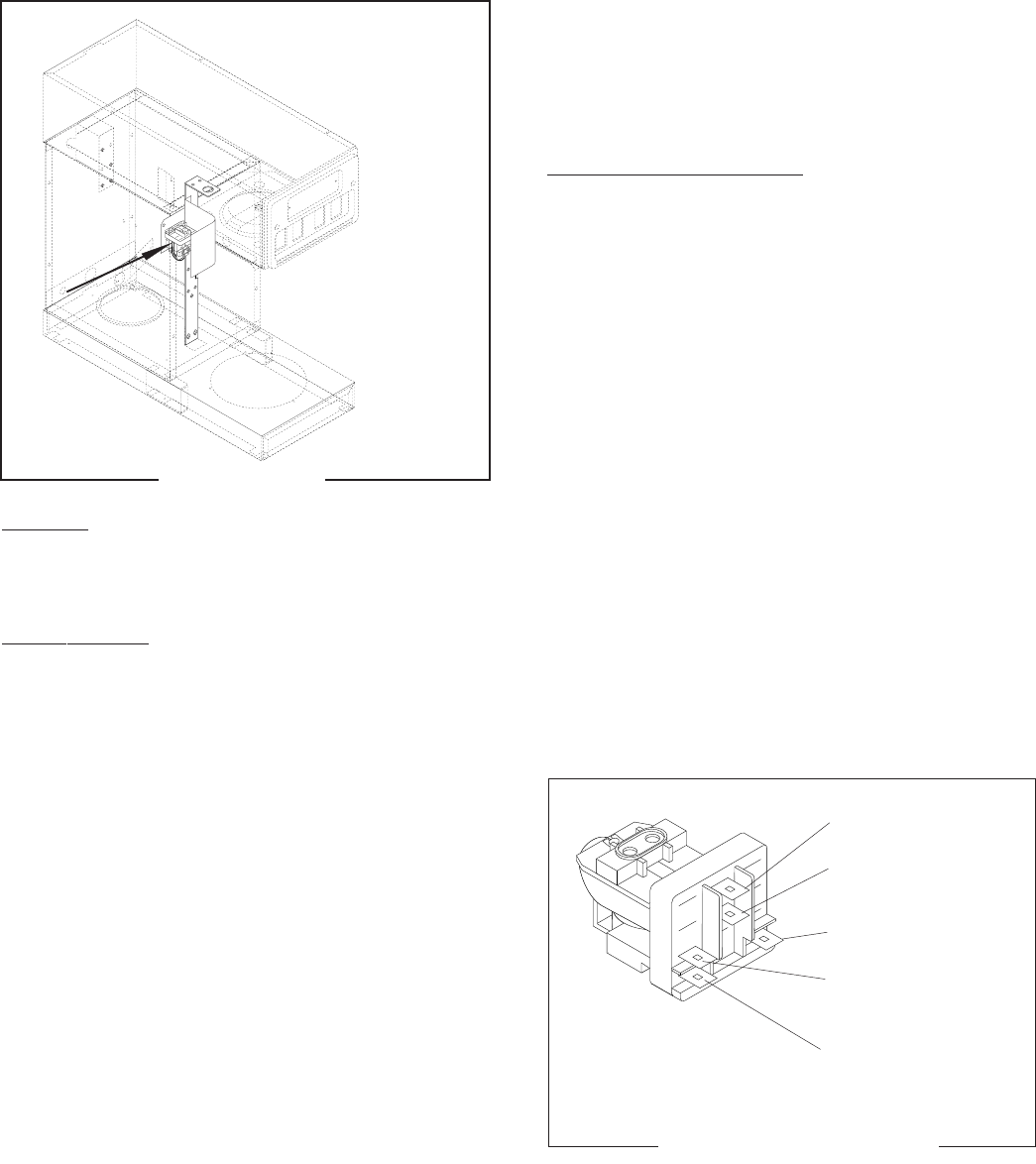
Location:
The relay is located inside the front access panel,
near the top of the bracket, FIG. 18.
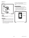
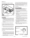
Test Procedure:
1. Disconnect the brewer from the power source.
2. Remove the brown/black wire from the “A” ter-
minal and the white wire from the “B” terminal on
the relay.
3. Check for continuity across the “A” and “B”
teminals.
If continuity is present as described, reconnect the
brown/black wires and white wires to the relay, FIG.
19, and proceed to #4.
If continuity is not present as described, replace the
relay.
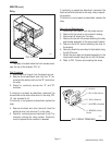
4. Remove the black wire from terminal 5 and the
white/red wire from terminal 7 on the relay.
5. Check for continuity across terminals 5 and 7 by
manually closing the relay contact. Continuity
must be present when contact is released.
If continuity is present as described, reconnect the
black and white/red wires to the relay, relay is operat-
ing properly.
If continuity is not present as described, replace the
relay.
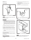
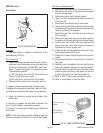
Removal and Replacement:
1. Disconnect the brewer from the power source.
2. Remove the top cover or top warmer housing.
3. Disconnect all wires from the relay.
4. Remove the two #8-32 screws attaching the relay
and bracket assembly to the component bracket.
5. Remove the #6-32 screw attaching the relay to
the bracket.
6. Securely attach the new relay to the bracket using
the #6-32 screw.
7. Attach the new relay and bracket assembly to the
component bracket using the two #8-32 screws.
8. Refer to FIG. 19 when reconnecting the wires.
(Added November 1999)
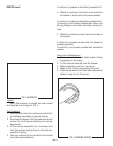
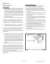
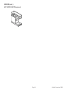
FIG. 19 RELAY TERMINALS
P1597
2 - No Wire
5 - BLK to Start Switch
B - WHI to Solenoid
7 - WHI/RED to Solenoid
A - BRN/BLK to Start
Switch