


Page 23
SERVICE (cont.)
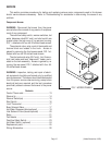
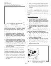
Water Level and Overflow Safety Switch
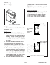
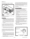
FIG. 22 WATER LEVEL and OVERFLOW
SAFETY SWITCHES
P2016
Location:
The water level and overflow safety switches are
located under the top cover or top warmer housing
and inside and front of the tank fill basin, FIG. 22.
Test Procedure:
1. Disconnect the brewer from the power source.
2. Remove the top cover or top warmer housing.
3. Remove the leads of the switch being tested from
the connection block mounted on the front of the
tank basin.
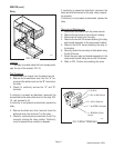
4. Check the voltage across the black lead of the con-
nection block and the white lead on the solenoid
coil with a voltmeter. Turn the On/Lower switch to
the “ON” position and connect the brewer to the
power source. The indication must be 120 volts
ac for two wire 120 volt models and three wire
120/240 volt models,
5. Disconnect the brewer from the power source.
If voltage is present as described, proceed to #6.
If voltage is not present as described, refer to the Wir-
ing Diagrams and check the brewer wiring harness.
6. Check for continuity across the overflow switch
red wires only until the plastic float is raised and
check that continuity returns when the float is low-
ered again.
7. Check for continuity across the water level switch
red wires only until the plastic float is raised and
check that continuity returns when the float is low-
ered again.
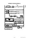
If continuity is present as described, reconnect the
wires as shown in FIG. 23, the switches are operating
properly.
If continuity is not present as described, replace the
switch.
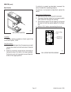
Removal and Replacement:
1. Disconnect the brewer from the power source.
2. Remove the top cover or top warmer housing.
3. Remove the wire leads connecting the water level
and overflow switches to the connection block at
the front of the tank and fill basin.
4. Disconnect the #8-32 screw and remove the en-
tire switch assembly from the tank and fill basin.
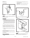
5. Place the new switch assembly into the bracket,
wires up.
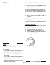
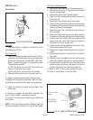
NOTE- The magnets must be at the top of the float
and there must be NO adjusting washers installed for
the overflow safety switch to operate properly.
6. Install the nuts over the wires and secure the
switch to the mounting bracket. Do not over
tighten.
7. Attach the entire switch assembly to the tank and
fill basin using the #8-32 screw.
8. Add or remove washers to the float on the level
switch as required. Adding washers increases the
volume, removing washers decreases it.
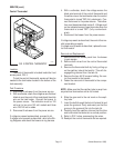
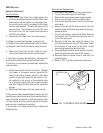
9. Refer to FIG. 23 and the relative wiring diagram
when reconnecting wires.
FIG. 23 WATER LEVEL and OVERFLOW
SAFETY SWITCH WIRING
P1478