


Page 17
P2014
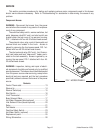
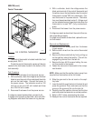
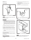
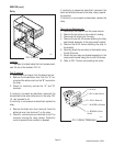
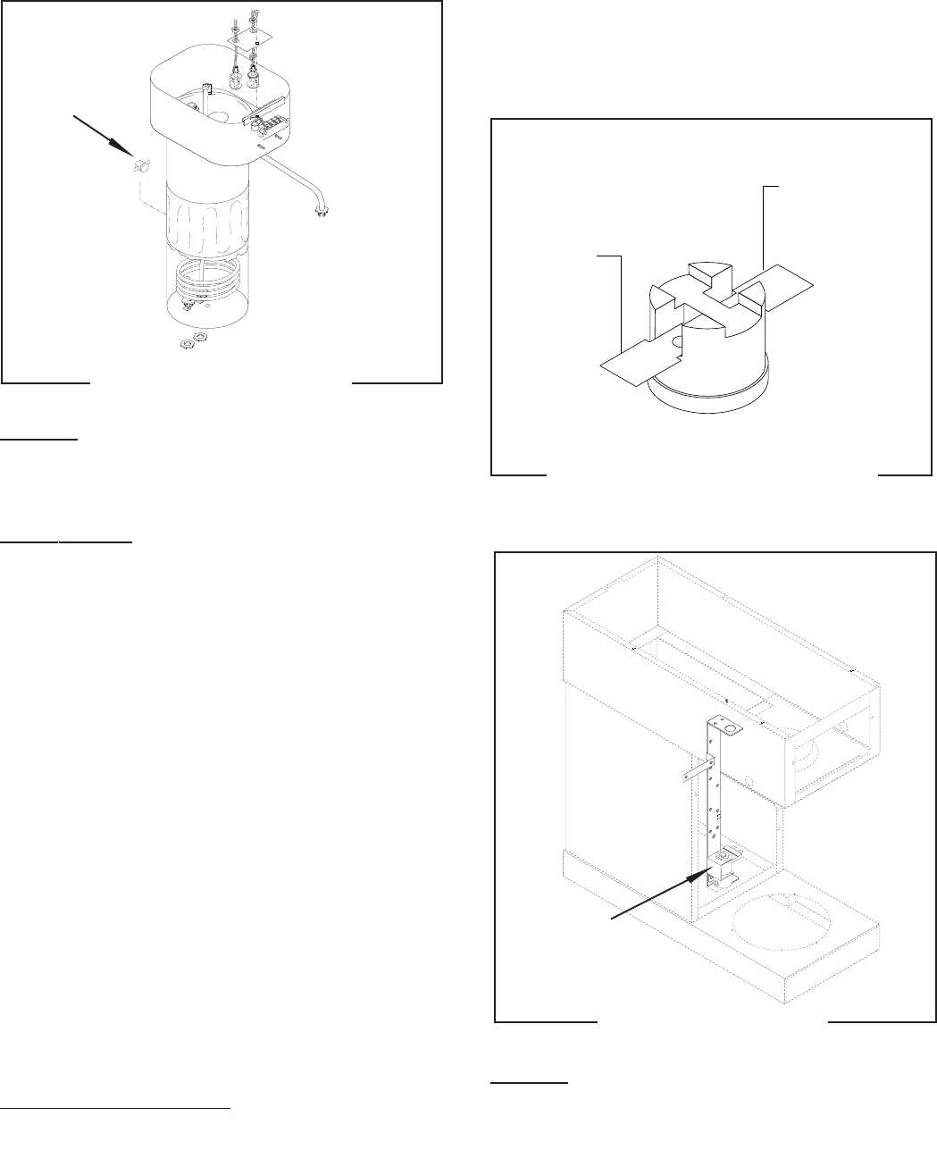
FIG. 10 LIMIT THERMOSTAT
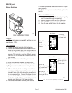
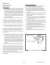
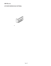
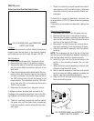
FIG. 11 LIMIT THERMOSTAT WIRING
SERVICE (cont.)
Limit Thermostat
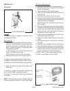
2. Carefully slide the limit thermostat out from un-
der the retaining clip.
3. Carefully slide the new limit thermostat into the
retaining clip.
4. Refer to FIG. 11 when reconnecting the wires.
Location:
The limit thermostat is located on the back of the
tank assembly, FIG. 10.
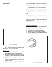
Test Procedure:
1. Disconnect the brewer from the power source.
2. Check voltage across the black wire from the limit
thermostat and the white wire on the tank heater
terminal. Connect the brewer to the power source.
The indication must be 120 volts ac for two wire
120 volt models and three wire 120/240 volt mod-
els.
3. Disconnect the brewer from the power source.
If voltage is present as described, proceed to #4.
If voltage is not present as described, refer to the Wir-
ing Diagrams and check the brewer wiring harness.
4. Check for continuity across the limit thermostat
terminals.
If continuity is present as described, the limit thermo-
stat is operating properly.
If continuity is not present as described, replace the
limit thermostat.
Removal and Replacement:
1. Remove both wires from the limit thermostat ter-
minals.
P1715
P1984
(Added November 1999)
BLK to Tank
Heater
BLU/BLK to Control
Thermostat
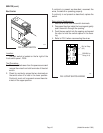
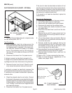
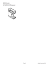
Solenoid Valve
Location:
The solenoid valve is located inside the front access
panel, near the bottom of the bracket, FIG. 12
FIG. 12 SOLENOID VALVE