


Page 20
SERVICE (cont.)
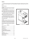
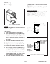
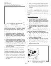
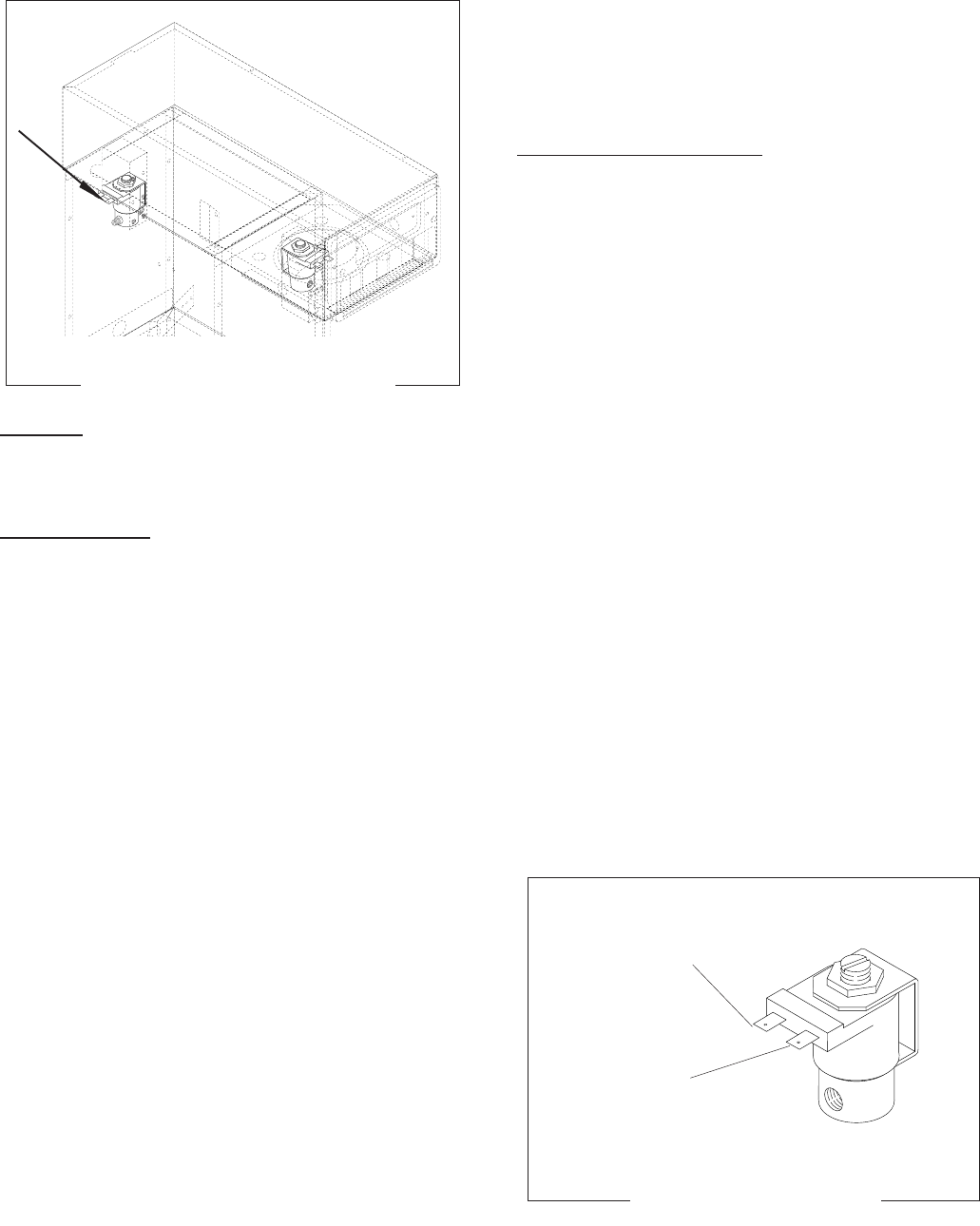
INLET SOLENOID VALVE (FAUCET - OPTIONAL)
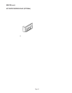
FIG. 16 INLET SOLENOID VALVE
(FAUCET)
P2021
Location:
The Inlet Solenoid Valve (faucet) is located inside
the rear access panel, FIG. 16.
Test Procedures:
1. With a voltmeter check the voltage across the
white and the white/violet wires when the hot wa-
ter dispense switch is pressed to the lower posi-
tion and held. Connect the brewer to the power
source. The indication must be 120 volts ac for
two wire 120 volt models and three wire 120/240
volt models.
2. Disconnect the brewer from the power source.
If voltage is present as described, proceed to #3.
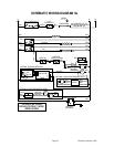
If voltage is not present as described, refer to the Wir-
ing Diagrams and check the brewer wiring harness.
3. Remove all wires from the coil. Check for conti-
nuity across the solenoid valve coil terminals.
If continuity is present as described, reconnect the
white and the white/violet wires and proceed to #4.
If continuity is not present as described, replace the
solenoid valve.
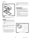
4. Check the solenoid valve for coil action. Connect
the brewer to the power source, place the hot water
dispense switch in the lower position and release.
Listen carefully in the vicinity of the solenoid valve
for a “clicking” sound as the coil magnet attracts
and repels the plunger.
5. Disconnect the brewer from the power source.
P2022
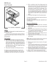
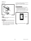
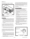
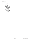
FIG. 17 INLET SOLENOID
VALVE WIRING
WHI/VIO to Hot Water
Dispense Valve
WHI to Hot Water
Dispense Valve
(Added November 1999)
If the sound is heard as described and water will not
pass through the solenoid valve, there may be a block-
age in the water line before or after the solenoid valve
or, the solenoid valve may require inspection for wear,
and removal of waterborne particles.
If the sound is not heard as described, replace the
solenoid valve.
Removal and Replacement:
1. Disconnect the brewer from the power source.
2. Turn off the water supply to the brewer.
3. Remove the rear access panel to gain access.
4. Disconnect all wires from the solenoid valve.
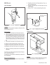
5. Turn the needle valve handle clockwise to close
the needle valve.
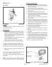
6. Disconnect the water lines to and from the sole-
noid valve.
7. Remove the two #8-32 screws which hold the
solenoid valve and mounting bracket to the com-
ponent bracket.
8. Lift out the solenoid valve and bracket. Remove
the bracket from the solenoid valve and save to
mount the new valve.
9. Securely install the new solenoid valve to the
mounting bracket with two #10-32 screws. Check
the direction of flow arrow on the valve. It must
be pointing toward the needle valve.
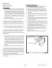
10. Securely attach the valve and bracket to the com-
ponent bracket using the two #8-32 screws.
11. Securely fasten the water lines to and from the
solenoid valve.
12. Refer to FIG. 17 when reconnecting the wires.
13. Refer to Initial Set-Up for readjustment of the
needle valve (steps 18-20).