


Page 15
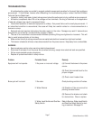
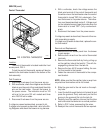
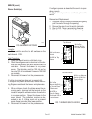
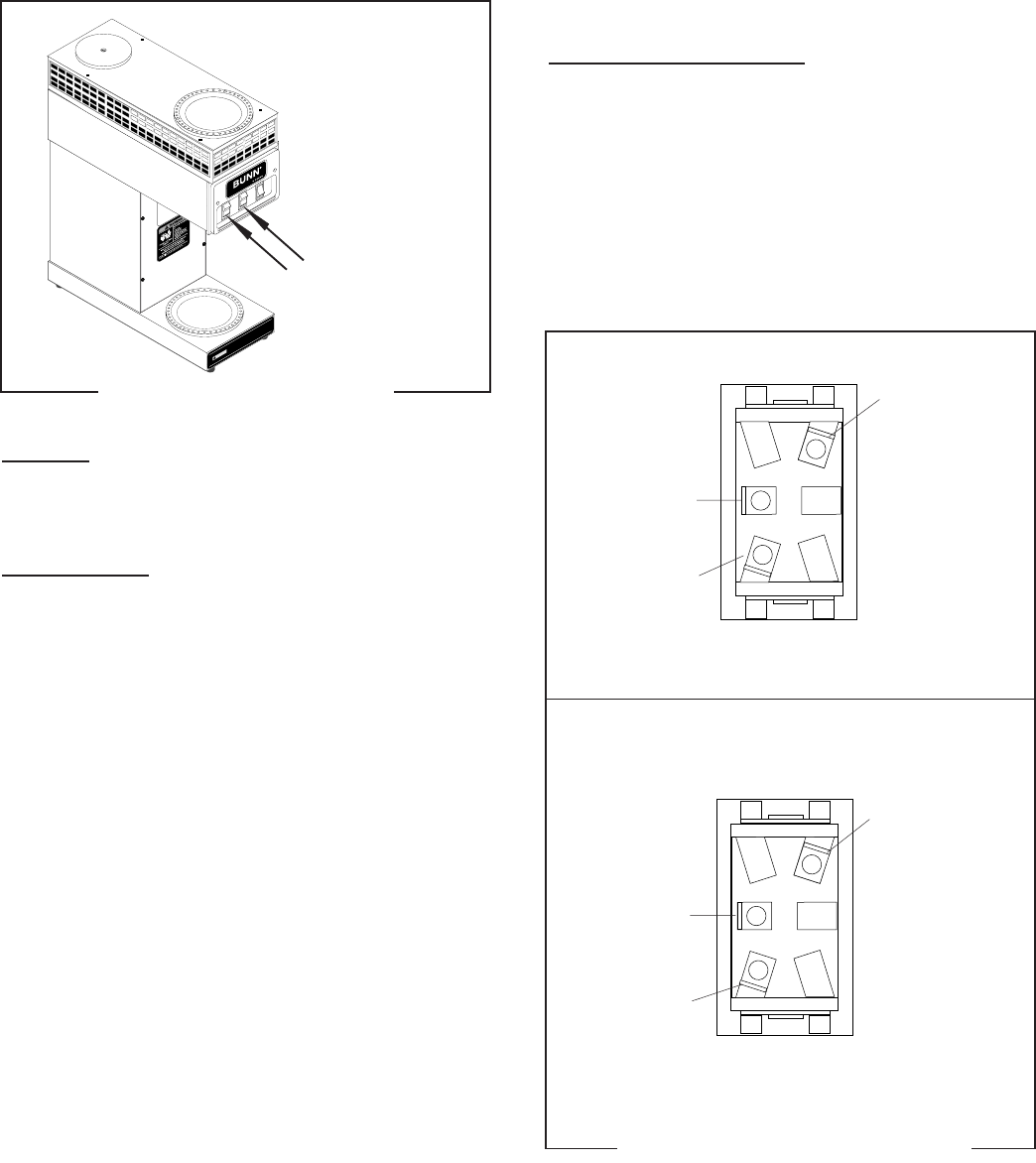
FIG. 6 WARMER SWITCHES
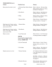
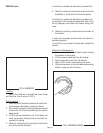
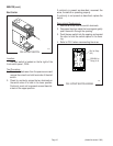
FIG. 7 WARMER SWITCH WIRING
SERVICE (cont.)
Warmer Switch(es)
If voltage is present as described the switch is oper-
ating properly.
If voltage is not present as described, replace the
switch.
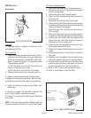
Removal and Replacement:
1. Compress the clips inside the housing and gently
push the switch through the opening.
2. Remove the wires from the switch terminals.
3. Refer to FIG. 7 when reconnecting the wires.
4. Push the new switch firmly into the opening.
Location:
These switches are the two left switches on the
switch panel, FIG 6.
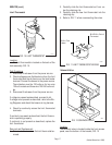
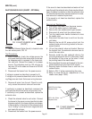
Test Procedure:
1. Locate the switch terminal with black wires.
2. Check the voltage across this terminal and the ter-
minal on the indicator lamp with white wire with a
voltmeter. Connect the brewer to the power
source. The indication must be 120 volts ac for
two wire 120 volt models and three wire 120/240
volt models.
3. Disconnect the brewer from the power source.
If voltage is present as described, proceed to #4.
If voltage is not present as described, refer to the Wir-
ing Diagrams and check the brewer wiring harness.
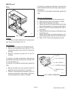
4. With a voltmeter, check the voltage across the re-
maining switch terminal and the terminal on the
indicator lamp with white wire when the switch is
in the upper position. Connect the brewer to the
power source. The indication must be as de-
scribed in step 2. Voltage must not be present
across these terminals in the lower position.
5. Disconnect the brewer from the power source.
P2012
(Added November 1999)
1
0
0
4
3
.
0
0
0
0
D
3
/
9
7
©
1
9
8
8
B
U
N
N
-
O
-
M
A
T
I
C
C
O
R
P
O
R
A
T
I
O
N
W
H
I
B
L
U
L
I
M
I
T
T
H
E
R
M
O
S
T
A
T
S
W
.
&
T
H
E
R
M
O
S
T
A
T
T
A
N
K
H
E
A
T
E
R
N
B
L
K
L
1
B
L
K
W
H
I
P
1
P
3
P
2
P
1
,
P
2
,
&
P
3
A
R
E
P
I
N
S
O
F
A
P
O
L
A
R
I
Z
E
D
T
H
R
E
E
-
P
I
N
C
O
N
N
E
C
T
O
R
.
G
R
E
E
N
S
C
H
E
M
A
T
I
C
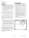
W
I
R
I
N
G
D
I
A
G
R
A
M
S
"
K
E
E
P
W
A
R
M
"
H
E
A
T
E
R
5
0
W
W
H
I
T
O
P
R
E
A
R
W
A
R
M
E
R
1
0
0
W
W
H
I
W
H
I
B
L
K
B
L
U
/
B
L
K
T
O
P
F
R
O
N
T
W
A
R
M
E
R
1
0
0
W
W
H
I
B
L
K
B
R
N
/
B
L
K
L
O
W
E
R
W
A
R
M
E
R
1
0
0
W
W
H
I
W
H
I
B
L
K
B
L
U
/
B
L
K
B
R
N
/
B
L
K
W
H
I
1
2
0
V
O
L
T
S
A
C
2
W
I
R
E
S
I
N
G
L
E
P
H
A
S
E
6
0
H
Z
1
4
2
5
W
W
H
I
/
V
I
O
!
C
A
U
T
I
O
N
W
A
R
M
E
R
S
A
N
D
S
U
R
F
A
C
E
S
A
R
E
H
O
T
T
OP FRONT
ON / LOWE
R
START
TOP RE
AR
LOWER
TOP FRONT
TOP REAR
Top Warmer
On/Lower Warmer
WHI to Top
Warmer, WHI to
On/Lower Switch
BLK to On/Lower
Switch
BLU/BLK to Top
Warmer
WHI to Top Warmer
Switch and WHI to
Terminal Block
(White Insert)
BLK to Top
Warmer and BLK
to Terminal Block
(Black Insert)
WHI/RED to
Overflow Safety
Switch and VIO to
Lower Warmer
P1590