


Page 13
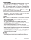
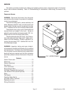
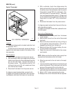
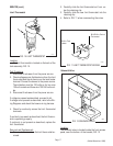
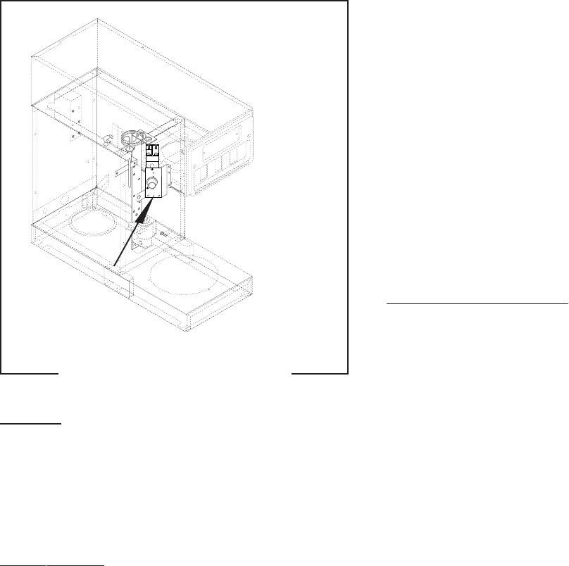
FIG. 2 CONTROL THERMOSTAT
SERVICE (cont.)
Control Thermostat
Location:
The control thermostat is located inside the front
access panel, FIG. 2.
To test the control thermostat, access will also be
needed to the tank heater located in the bottom of the
tank assembly.
Test Procedure:
1. Disconnect the brewer from the power source.
2. With a voltmeter, check the voltage across the blue/
black wire on the control thermostat and the white
wire on the tank heater. Connect the brewer to
the power source. The indication must be 120
volts ac for two wire 120 volt models and three
wire 120/240 volt models.
3. Disconnect the brewer from the power source.
If voltage is present as described, proceed to #4.
If voltage is not present as described, refer to the Wir-
ing Diagrams and check the brewer wiring harness.
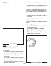
4. With a voltmeter, check the voltage across the
black wire terminal of the control thermostat and
the white wire on the tank heater when the control
thermostat is turned "ON" (fully clockwise). Con-
nect the brewer to the power source. The indica-
tion must be as described in step 2. Voltage must
not be indicated across these terminals when the
thermostat is turned "OFF" (fully counterclock-
wise).
5. Disconnect the brewer from the power source.
If voltage is present as described, the control thermo-
stat is operating properly.
If voltage is not present as described, replace the con-
trol thermostat.
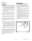
Removal and Replacement:
1. Remove the front access panel from the brewer
to gain access.
2. Remove both wires from the control thermostat
terminals.
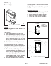
3. Remove the thermostat bulb by firmly pulling-up
on the capillary tube at the tank lid. This will dis-
engage the grommet from the tank lid.
4. Remove the two #8-32 screws holding the con-
trol thermostat to the bracket.
5. Fasten the new control thermostat to the compo-
nent bracket.
NOTE - Make sure that the capillary tube is away from
any electrical termination and is not kinked.
6. Slide the grommet to the red mark on the capil-
lary tube.
7. Insert the bulb through the hole in the tank lid and
press the grommet firmly and evenly so that the
groove in the grommet fits into the tank lid.
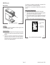
8. Carefully bend the capillary tube so that the tube
and bulb inside the tank are in a vertical position.
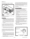
9. Refer to FIG. 3 when reconnecting the wires.
10. Readjust the control thermostat dial as required.
P1478
(Added November 1999)