


16
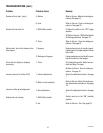
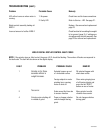
SERVICE (cont.)
Hopper Selector Switch (cont.)
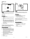
Test Procedure:
1. Disconnect grinder from the power supply.
2. Remove all wires from the switch terminals.
3. Place the selector switch in the left position.
4. Check for continuity across the center and right
terminals on the rear of the switch.
5. Continuity must not present across the center
and left terminals on the rear of the switch.
6. Check the bottom row, then the top row of ter-
minals.
If continuity is present as described proceed to #7.
If continuity is not present as described, replace the
switch.
7. Place the selector switch in the right position.
8. Check for continuity across the center and left
terminals on the rear of the switch.
9. Continuity must not be present across the cen-
ter and right terminals on the rear of the switch.
10. Check the bottom row , then the top row of ter-
minals.
If continuity is present as described, reconnect the
wires, the switch is operating properly.
If continuity is not present as described, replace the
switch.
Removal and Replacement:
1. Remove all wires from the switch terminals.
2. Compress the clips inside the front of the hous-
ing and gently push the switch through the open-
ing.
3. Push the new switch into the opening and spread
the clips to retain the switch in the housing.
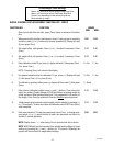
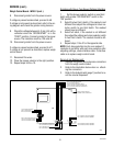
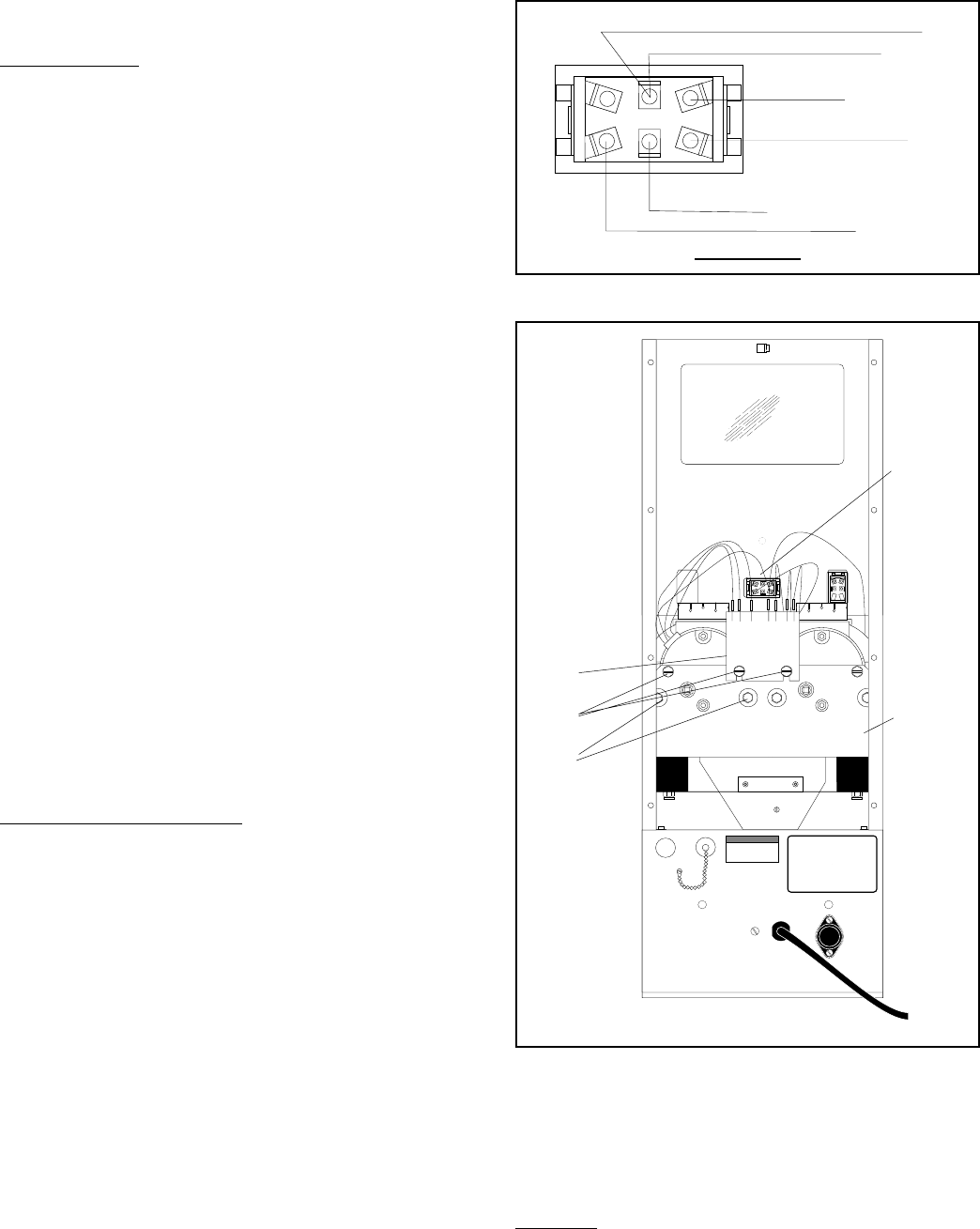
4. Refer to the following illustration when re- con-
necting the wires.
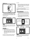
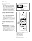
PNK TO OFF/ON/ START SWITCH
YEL TO J1- 1
BLU TO RIGHT MOTOR
VIO TO J4 - 3
WHI/ BLU TO LEFT MOTOR
PNK TO OPTIONAL MULTISET SWITCH
REAR VIEW
P742
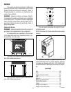
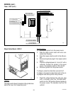
Motors
NOTICE
For connection to Bunn-Omatic
Coffee Brewer Models:
Dual, OT, Single, & System III only.
(24 volt N.E.C. Class 2 circuit only.)
BUNN
M
A
N
U
F
A
C
T
U
R
E
D
B
Y
B
U
N
N
-
O
-
M
A
T
IC
C
O
R
P
O
R
A
T
IO
N
S
P
R
IN
G
F
IE
L
D
, IL
L
IN
O
IS
, U
.S
.A
.
M
O
D
E
L
S
/N
V
O
L
T
S
A
.C
. A
M
P
W
A
T
T
S
P
H
A
S
E
W
IR
E
H
E
R
T
Z
C
O
V
E
R
E
D
U
N
D
E
R
O
N
E
O
R
M
O
R
E
O
F
T
H
E
F
O
L
L
O
W
IN
G
P
A
T
E
N
T
S
:
O
N
E
O
R
M
O
R
E
O
T
H
E
R
P
A
T
E
N
T
S
M
A
Y
B
E
P
E
N
D
IN
G
1
2
3
4
5
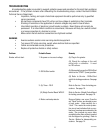
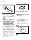
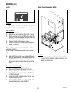
REAR VIEW
P743
1. Motor Circuit Assembly
2. Motor & Circuit Assembly Mounting Screws
3. Motor Mounting Screws
4. Hopper Selector Switch
5. Motor Mounting Bracket
Location:
The motors are located in the center part of the
housing just below the hopper.
10854 030300