


18
SERVICE (cont.)
Motor (cont.)
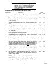
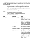
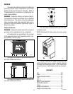
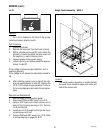
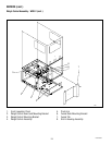
Removal and Replacement - GRIND CHAMBER
H
G
D
C
B
F E A
COARSE FINE
T
H
O
R
O
U
G
H
L
Y
C
L
E
A
N
G
R
I
N
D
C
H
A
M
B
E
R
B
E
F
O
R
E
R
E
A
S
S
E
M
B
L
Y
E
M
P
T
Y
H
O
P
P
E
R
B
E
F
O
R
E
R
E
M
O
V
I
N
G
T
H
I
S
C
O
V
E
R
.
N
O
T
I
C
E
COARSE FINE
C
O
A
R
S
E
-
F
I
N
E
B
U
N
N
COARSE FINE
T
H
O
R
O
U
G
H
L
Y
C
L
E
A
N
G
R
I
N
D
C
H
A
M
B
E
R
B
E
F
O
R
E
R
E
A
S
S
E
M
B
L
Y
E
M
P
T
Y
H
O
P
P
E
R
B
E
F
O
R
E
R
E
M
O
V
I
N
G
T
H
I
S
C
O
V
E
R
.
N
O
T
I
C
E
COARSE FINE
C
O
A
R
S
E
-
F
I
N
E
B
U
N
N
20667.0000
20666.0000
P744
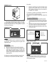
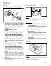
1. Remove the two 1/4"-20 screws (A) holding the
front cover (B) to the burr housing (H). Carefully
remove the burr housing front cover with adjust-
ing screw and nut. Inspect adjusting screw to
see if worn.
Replace if excessively worn or
damaged.
2. Remove load disc (C) from burr auger rotor/
spring assembly (D). Inspect disc to see if worn.
Replace if excessively worn or damaged.
3. Carefully remove burr auger rotor/spring assem-
bly (D) from burr housing (H). Inspect burr for
wear.
Replace if excessively worn or damaged.
4. Remove bushing (E) and washer (F) from motor
shaft.
5. Remove the two 1/4"-20 screws attaching sta-
tionary burr (G) to burr housing (H). Remove
and inspect burr for wear.
Replace if excessively worn or damaged.
6. Inspect the grind chamber and remove any for-
eign materials. The burrs will not properly seat
in the chamber if any material or coffee particles
remain.
7. Reinstall the stationary burr (G), washer (F),
bushing (E), burr auger rotor/spring
assembly(D), load disc(C) and burr housing front
cover(B) with adjusting screw and nut to the burr
housing(H).
8. Refer to
Adjustments
section (page 7) to vary
the grind dispensed.
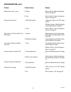
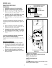
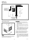
Motor Circuit Assembly
Location:
The motor circuit assembly is located on the
rear of motor mounting bracket.
P750
Test Procedure:
1. The motor circuit assembly is a line filter for
motor electrical noise.
2. If the timer settings are erratic or change replace
the motor circuit assembly board.
Removal and Replacement:
1. Remove all wires.
2. Loosen the two #10-32 slotted hex head screw
and lift motor circuit assembly off.
3. Install new motor circuit assembly between head
of screws and external tooth lockwashers.
Tighten screws.
4. Refer to
Wiring Diagram
(pages 24 & 25) and
reinstall wires.
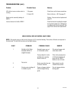
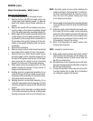
DISPENSE TIM
E (Seco
nds)
DISPLAY
Increase
Decrease
R
e
a
d
o
u
t
w
ill b
e
d
is
p
l
a
y
e
d
f
o
r
5
m
in
u
t
e
s
.
T
im
e
r c
a
n
o
n
ly
b
e
a
d
ju
s
t
e
d
w
h
ile
re
a
d
o
u
t is
d
is
p
la
y
e
d
.
+
W
A
R
N
IN
G
H
A
Z
A
R
D
O
U
S
V
O
L
T
A
G
E
UNPLUG
GR
IN
DER
BEFO
RE
REM
OVIN
G
01516.0000
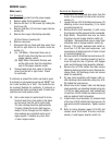
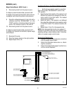
Timer - DG-2
Location:
The timer is located on the grinder base, behind
the lower front inspection panel.
P745
10854 030300