


25
SERVICE (cont.)
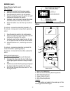
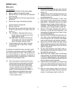
Weigh Control Assembly - WDG-2 (cont.)
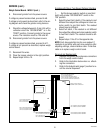
Removal and Replacement
1. Disconnect grinder from the power source.
2. Remove the four #6-32 truss head screws se-
curing lower front inspection panel (1). Remove
panel with digital control display assembly at-
tached.
3. Remove the one #6-32 truss head screw secur-
ing the weigh control board mounting bracket
(2) to the weigh assembly mounting bracket (3).
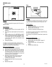
4. Slide weigh control board mounting bracket and
control board (2) out of weigh assembly mount-
ing bracket (3) far enough so the connectors on
the grinders main wiring harness and the con-
nector on the weight assembly leads can be dis-
connected.
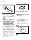
5. Disconnect connectors.
6. Remove weigh control board mounting bracket
and weigh control board (2) from the grinder.
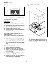
7. Remove the two #10-32 slotted head screws
securing weigh control mounting bracket (3) to
the base of the grinder and the two #10-32 keps
nuts securing the weigh control mounting
bracket (3) to the rear of the grinder housing.
8. Slide weigh control mounting bracket (3) from
grinder housing far enough to have access to
weigh control assembly (4).
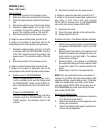
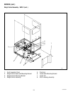
9. Holding pivot arm w/overload assembly (5) up
remove the four #8-32 pan head screws secur-
ing weigh control assembly (4). Remove and dis-
card weigh control assembly (4).
10. Holding pivot arm w/overload assembly (5) up
install the new weigh control assembly (4) to the
mounting bracket (3) using four #8-32 pan head
screws.
11. Slide weigh control assembly mounting bracket
(3) on to the two studs on the rear of the grinder
housing and secure with two #10-32 keps nuts.
NOTE - Carefully guide all wires while installing the
weigh mechanism. The funnel tab (7) on the fun-
nel rails mounting bracket (6) must be in clear-
ance slot (8) in the grinder housing and must
move freely up and down.
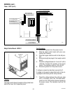
12. Secure weigh control assembly mounting bracket
(3) to grinder base with two #10-32 slotted head
screws.
13. Slide the weigh control bracket and weigh con-
trol board (2) into the weigh control mounting
bracket (3) far enough to reconnect the eight and
ten pin connectors from the main wiring harness
and the four pin connector from the weigh con-
trol assembly. Connect the wiring.
14. Refer to the illustration on page 19 when reat-
taching the connectors.
NOTE - Inspect for pinched wires.
15. Slide weigh control bracket and weigh control
board (2) the rest of the way into the weigh con-
trol mounting bracket (3) and secure with one
#6-32 truss head screw.
16. Reinstall lower front inspection panel with digi-
tal control display assembly attached using four
#6-32 truss head screws.
17. Connect the grinder to the power source and fol-
low the function list on page 8 for information
on setting the weight to be ground.
10854 030300