


20
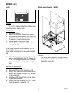
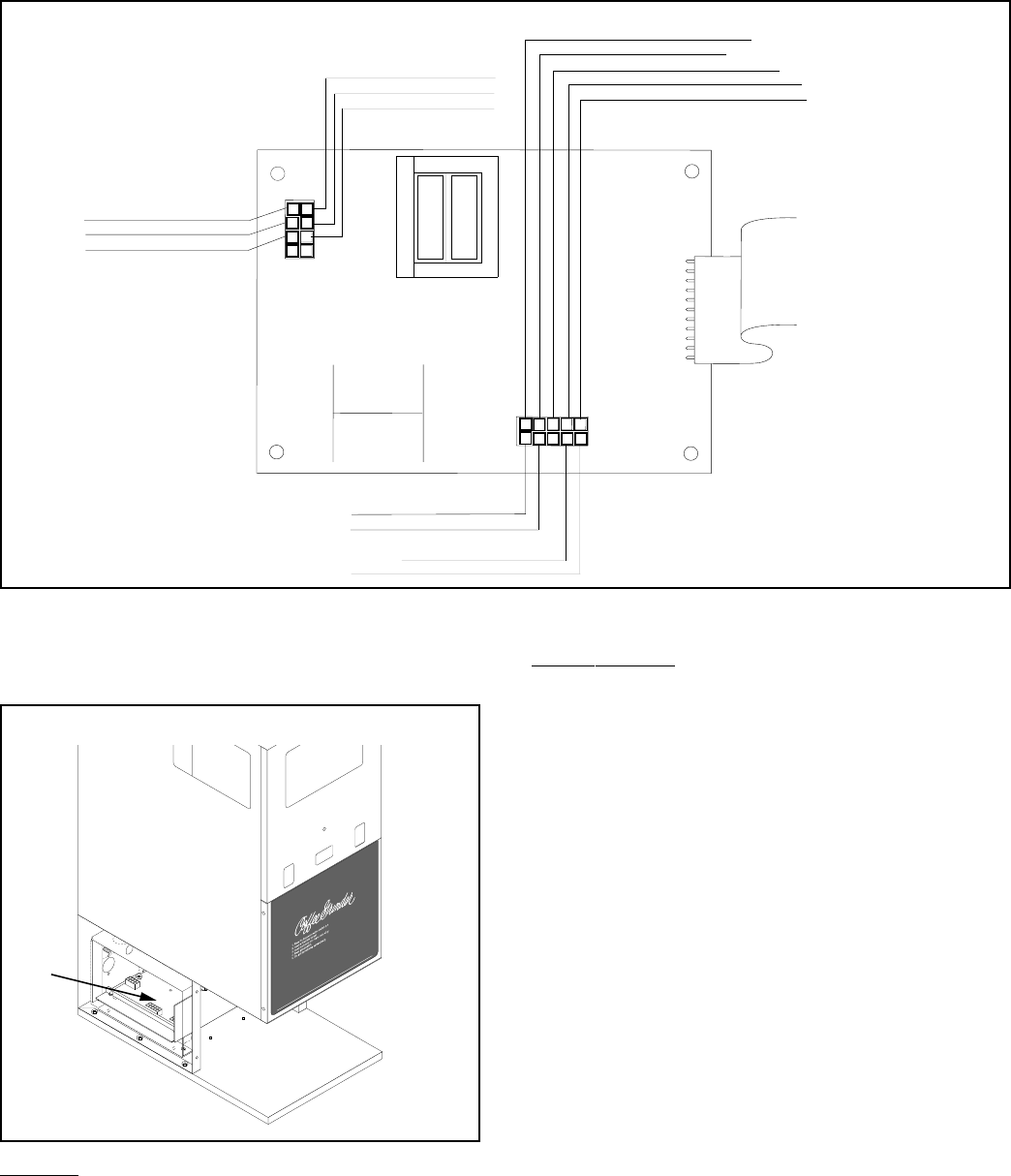
J4
1
2
3
4
5
6
7
8
J1
6
7
8
9
10
1
2
3
4
5
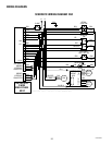
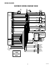
BLK TO FUSE HOLDER
WHI TO POWER CORD
VIO TO SELECTOR SWITCH
ORA TO OFF/ON/START SWITCH
ORA TO OFF/ON/START SWITCH
RED TO OFF/ON START SWITCH
YEL TO SELECTOR SWITCH
GRN TO OPTIONAL MULTISET SWITCH
TAN TO OPTIONAL INTERFACE CONNECTOR
GRY TO OPTIONAL INTERFACE CONNECTOR
TAN TO INTERFACE CONNECTOR
GRY TO INTERFACE CONNECTOR
BLK TO GRINDING LED
PNK TO INTERFACE CONNECTOR
RED TO MOTOR CIRCUIT BOARD
(Prior to S/N DG00002660)
WHI TO MOTOR CIRCUIT BOARD
(S/N DG00002660 - UP)
P746
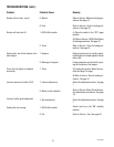
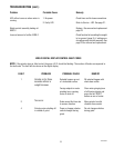
SERVICE (cont.)
Timer - DG-2 (cont.)
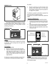
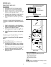
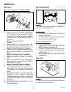
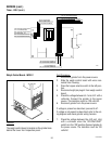
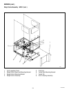
Weigh Control Board - WDG-2
P929
Location
The weigh control board is located on the grinder base
behind the lower front inspection panel.
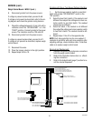
Test Procedure:
1. Disconnect grinder from the power source.
2. Slide the weigh control board with wires con-
nected from housing.
3. Place the hopper selector switch in the left posi-
tion.
4. Disconnect eight pin plug J4 from weigh control
board.
5. Check the voltage between J4-1 and J4-2 with a
voltmeter. Connect the grinder to the power
source. The indication must be 120 volts AC.
6. Disconect grinder from the power source.
If voltage is present as described, proceed to #7.
If voltage is not present as described, refer to the wir-
ing diagram and check grinder wiring harness.
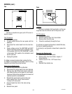
7. Check the voltage between the J4-2 and J4-6
with a voltmeter when the "OFF/ON/START"
switch is in the "ON" position.Connect grinder to
the power source. The indication must be 120
volts AC.
10854 030300