


22
SERVICE (cont.)
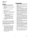
Fan
Use only on a properly protected circuit
capable of the rated load.
Electrically ground the chassis.
Follow national/local electrical codes.
Do not use near combustibles.
WARNING
P747
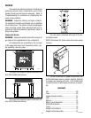
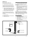
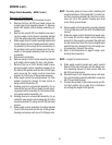
The fan is mounted on upper part of the rear in-
spection panel.
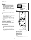
Test Procedure:
1. Unplug the grinder.
2. To gain access remove the rear panel with fan
attached.
3. Disconnect fan motor leads from the main har-
ness.
4. Check voltage across the WHT/RED and WHT
leads to the main harness with a voltmeter. Plug-
in the grinder. With the "OFF/ON/START" switch
in the center "ON" position the indication must
be 120 volts AC.
5. Unplug the grinder.
If voltage is present as described, replace the fan.
If voltage is not present as described, refer to wiring
diagrams and check the wiring harness.
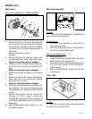
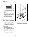
Location:
Removal and Replacement:
1. Remove rear panel with fan attached.
2. Disconnect fan motor leads from main harness
3. Remove four #6-32 flat head screws and lock-
nuts attaching fan and fan guard to rear inspec-
tion panel. Discard fan and set guard, screws and
locknuts aside for reinstallation.
4. Reinstall fan guard and new fan to the rear
panel making sure the air flow direction
is away from rear panel.
5. Connect leads from fan to the main wiring
harness.
6. Reinstall rear panel.
Fuse
NOTICE
For connection to Bunn-Omatic
Coffee Brewer Models:
Dual, OT, Single, & System III only.
(24 volt N.E.C. Class 2 circuit only.)
BUNN
M
A
N
U
F
A
C
T
U
R
E
D
B
Y
B
U
N
N
-O
-
M
A
T
IC
C
O
R
P
O
R
A
T
IO
N
S
P
R
I
N
G
F
I
E
L
D
, I
L
L
IN
O
IS
,
U
.S
.A
.
M
O
D
E
L
S
/N
V
O
L
T
S
A
.
C
.
A
M
P
W
A
T
T
S
P
H
A
S
E
W
I
R
E
H
E
R
T
Z
C
O
V
E
R
E
D
U
N
D
E
R
O
N
E
O
R
M
O
R
E
O
F
T
H
E
F
O
L
L
O
W
IN
G
P
A
T
E
N
T
S
:
O
N
E
O
R
M
O
R
E
O
T
H
E
R
P
A
T
E
N
T
S
M
A
Y
B
E
P
E
N
D
I
N
G
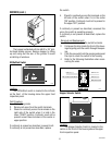
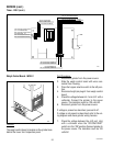
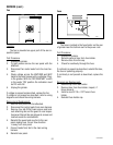
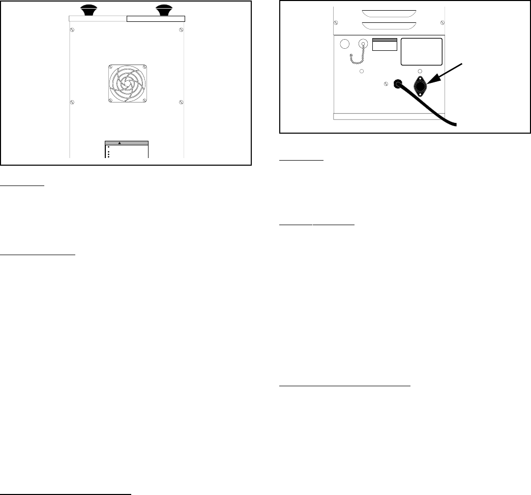
Location:
The fuse is located in the fuse holder on the rear
of grinder near the bottom next to the power cord.
Test Procedure:
1. Unplug the grinder.
2. Remove cap and fuse from fuse holder.
3. Remove fuse from the cap.
4. Check for continuity through the fuse.
If continuity is present as described, reinstall the fuse,
the fuse is operating properly.
If continuity is not present as described, replace the
fuse.
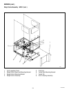
Removal and Replacement:
1. Remove cap from fuse holder.
2. Remove fuse from fuse holder, inspect, if
blown discard.
3. Install a new SC 10 x .312" fuse in fuse
holder.
4. Reinstall fuse holder cap.
P748
10854 030300