


17
SERVICE (cont.)
Motor (cont.)
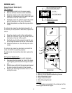
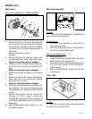
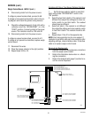
Test Procedure:
1. Disconnect grinder from the power supply.
2. Remove upper front inspection panel.
3. Remove the two 1/4"-20 screws (A) holding the
front cover (B).
4. Remove load disc (C) from burr auger rotor/as-
sembly (D).
5. Remove burr auger rotor/spring assembly
(D) from the burr housing (H).
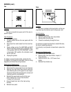
6. Remove rear panel.
7. Disconnect the red, black and blue wires from
the left or right motor to the motor circuit as-
sembly (1).
8. (A) Left Motor - Disconnect blue wire on
the left motor from the blue wire to the
hopper selector switch.
(B) Right Motor- Disconnect the blue wire
on the right motor from the white/blue
wire to the hopper selector switch.
9. Connect leads of an ohm meter to the blue
wires from the left or right motor. Check
for continuity.
If continuity is present the motor overload is good.
If continuity is not present press the red "RESET" but-
ton. Listen carefully for a "click". This resets the mo-
tor overload. Recheck for continuity. If continuity is
now present the motor overload is reset. If motor over-
load does not reset replace motor.
10. Set an ohm meter to read at least 10 ohms.
Connect leads from ohm meter to the black
and red wires from the left or right motor.
The ohm reading should be approximately
10 ohms. Rotate the motor shaft approxi -
mately 1/8 turn through one full rotation. If
ohm readings are consistent motor wind -
ings are good. If reading vary more than
±1 ohm, replace motor.
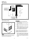
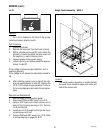
Removal and Replacement:
1. Disconnect red, black and blue wires from the
motor to be removed from the motor circuit as-
sembly (1).
2 Loosen the two #10-32 slotted head screws (2)
attaching motor circuit assembly (1) to motor
mounting bracket (5).
3. Remove motor circuit assembly (1) with wires
from harness and the opposite motor connected.
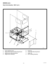
4. Right Motor - Disconnect blue wire on motor
from blue wire on hopper selector switch (4).
Left Motor - Disconnect blue wire on motor from
white/blue wire on hopper selector switch (4).
5. Using a 7/16" socket, extension and rachet re-
move two 1/4"-20 hex head capscrews and
lockwashers (3) attaching front of motor to front
of mounting bracket (5).
6. Remove two #10-32 slotted hex head screws (2).
7. Lift motor out of mounting bracket (5) and re-
move through the rear of grinder with hopper
collar and discharge chute assembly attached.
8. Remove four #10-24 slotted hex head screws
attaching discharge chute to motor. Remove dis-
charge chute. Set discharge chute and screws
aside for reassembly.
9. On new motor assembly with hopper collar in-
stall discharge chute assembly using four #10-
24 slotted hex head screws.
10. Mount new motor, hopper collar and discharge
chute assembly on mounting bracket using two
1/4"-20 hex head capscrews and lockwashers
(3) and two #10-32 slotted hex head screws (2)
and one external tooth lockwasher.
11. Install motor circuit assembly (1) between head
of the two #10-32 slotted hex head screws (2)
and external tooth lockwashers. Tighten screws
(2).
12. Refer to wiring diagram (pages 24 & 25) and
connect wires from motor to motor circuit as-
sembly (1) and hopper selector switch (4).
10854 030300