


19
SERVICE (cont.)
Timer - DG-2 (cont.)
Test Procedure:
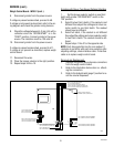
1. Disconnect grinder from the power source.
2. Slide timer with wires connected from housing.
3. Place the hopper selector switch in the left posi-
tion.
4. Disconnect eight pin plug J4 from timer board.
5. Check the voltage between J4-1 and J4-2 with
a voltmeter. Connect the grinder to the power
source. The indication must be 120 volts AC.
6. Disconnect grinder from the power source.
If voltage is present as described, proceed to #7.
If voltage is not present as described, refer to the
wiring diagram and check grinder wiring harness.
7. Check the voltage between J4-2 and J4-6 with
a voltmeter when the "OFF/ON/START" switch is
in the "ON" position.Connect the grinder to the
power source. The indication must be 120 volts
AC.
8. Disconnect grinder from the power source.
If voltage is present as described, proceed to #9.
If voltage is not present as described, refer to the
wiring diagram and check the grinder wiring harness.
9. Grinders prior to S/N DG00002660:
Check the voltage between J4-3 (+) and J4-5 (-
) with a voltmeter set to read DC voltage when
the "OFF/ON/START" switch is in the "START" po-
sition. The indication must be 110 volts DC mini-
mum.
Grinders S/N DG00002660 - UP
Check the voltage between J4-3 and J4-5 with a
voltmeter when the "OFF/ON/START" is in the
"START" position. The indication must be 120
volts AC.
10. Disconnect grinder from the power source.
If voltage is present as described, proceed to #11.
If voltage is not present as described, replace timer
and motor circuit board with part number
25725.1000.On grinders prior to S/N DG00002660
also order main wiring harness 25762.0001.
11. Reconnect the wires.
12. Place the hopper selector in the right position.
13. Repeat steps #4 thru 10.
Grinders with One or Two Brewer Optional Interface
1. Set the brewer selector switch on one third batch
with grinder "OFF/ON/START" switch in the "ON"
position.
2. Select the two third's batch, if the readout is not
different then adjust the settings and return se-
lector switch to one third batch. The readout
should now be different.
3. Select full batch, if the readout is not different
then adjust the settings and return selector switch
to two third's batch. The readout should be dif-
ferent.
4. Repeat steps 1 thru 3 for the opposite side.
NOTE: Each brew selection has its own readout. If
readouts do not differ with each brew selection after
adjusting settings, check interface cable. If interface
cable is ok replace timer and motor circuit board
with part number 25725.1000. On grinders prior to
S/N DG00002660 also order main wiring harness
part number 25762.0001.
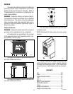
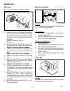
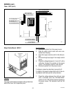
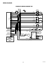
Removal and Replacement:
1. Separate the grinder wiring harness connectors
from the timer circuit board.
2. Refer to the illustration on next page when reat-
taching the connectors.
3. Refer to the
Adjustments
(page 7) section to re-
set the volume dispensed.
10854 030300