


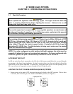
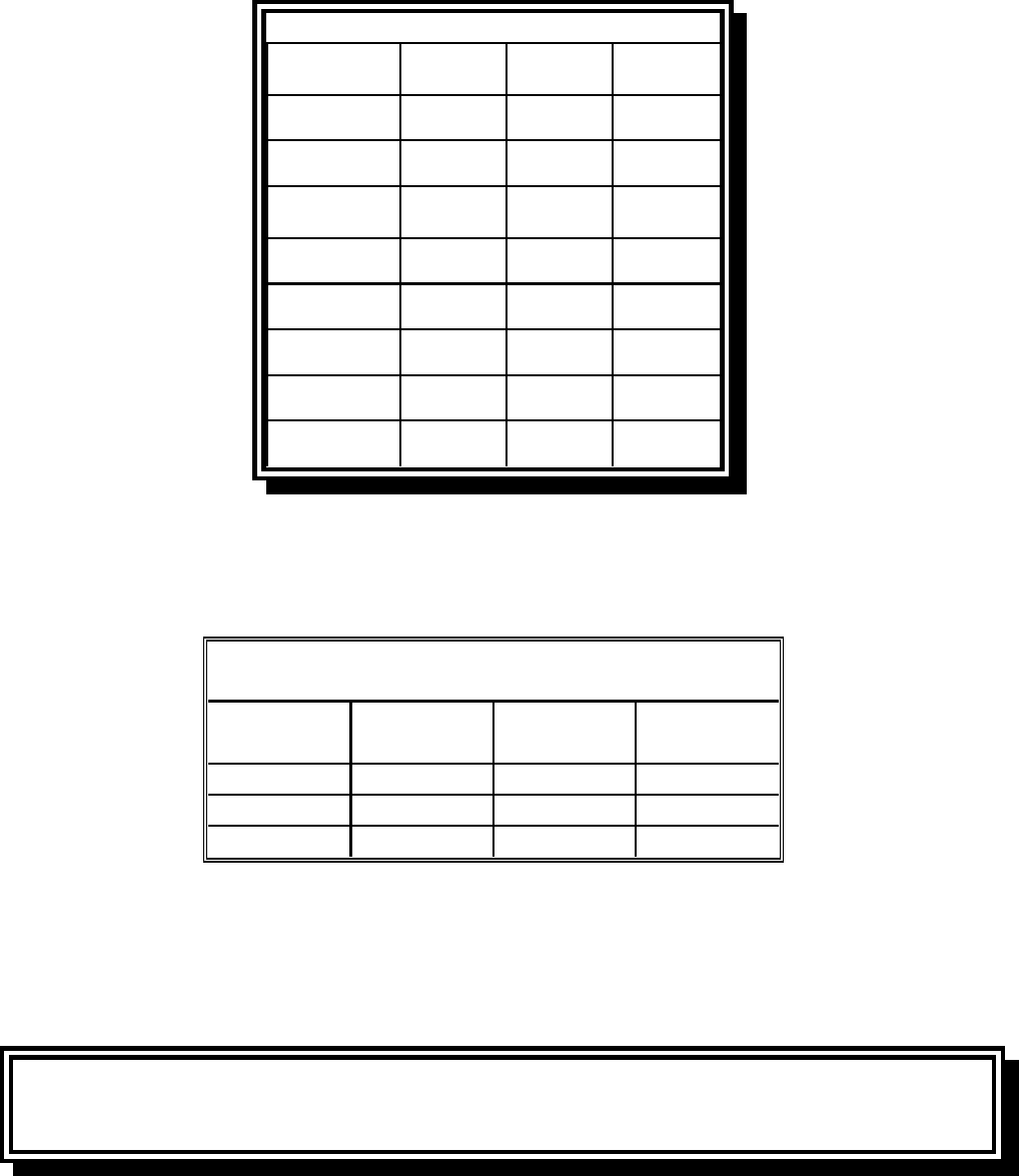
2-6
BE
I2E+(S)
I3P
G20/G25
G31
20/25
37
DE
I2 ELL
13P
G20/G25
G31
20
50
FR
II2Esi3P
G20/G25
G31
20/25
37 ET 50
LU
I2E G20/G25 20/25
ES
II2H3P
G20
G31
20
37 ET 50
NL
II2L3P
G25
G31
25
50
IE-PT-GB
II2H3P
G20
G31
20
37
DK-GR-IT
I2 H G20 20
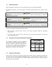
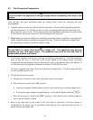
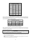
CE Approved Gas Categories
Country Category Gas
Pressure
(mbar)
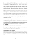
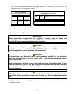
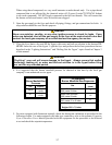
The size of the gas line used for installation is very important. If the line is too small, the gas
pressure at the burner manifold will be low. This may cause slow recovery and delayed ignition.
The incoming gas supply line should be a minimum of 1½” (38 mm) in diameter. Refer to the chart
below for the minimum sizes of connection piping.
Gas Connection Pipe Sizes
(Minimum incoming pipe size should be 1 1/2" (38 mm))
Natural
3/4" (19 mm)
1" (25 mm) 1 1/4" (33 mm)
Propane 1/2" (13 mm) 3/4" (19 mm) 1" (25 mm)
Manufactured 1" (25 mm) 1 1/4" (33 mm) 1 1/2" (38 mm)
Gas Single Unit 2 - 3 Units
4 or more
units*
* For distances of more than 20 feet (6 m) and/or more than 4
fittings or elbows, increase the connection by one pipe size.
Before connecting new pipe to your unit, the pipe must be thoroughly blown out to remove any
foreign particles. If these foreign particles get into the burner and controls, they will cause improper
and sometimes dangerous operation.
CE Standard
Ensure the combustion air supply airflow is 2m
3
/h times the kW rating of the fryer.
(See the rating plate affixed to the fryer door for the kW rating.)
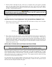
1. Connect the quick-disconnect hose to the fryer quick-disconnect fitting under the front of the
fryer and to the building gas supply-line.
NOTE: Some fryers are configured for a rigid connection to the gas supply line. These units are
connected to the gas supply line at the rear of the unit.