


1-7
8. Reconnect the element connector ensuring that the latches lock.
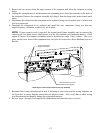
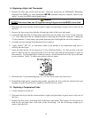
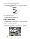
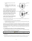
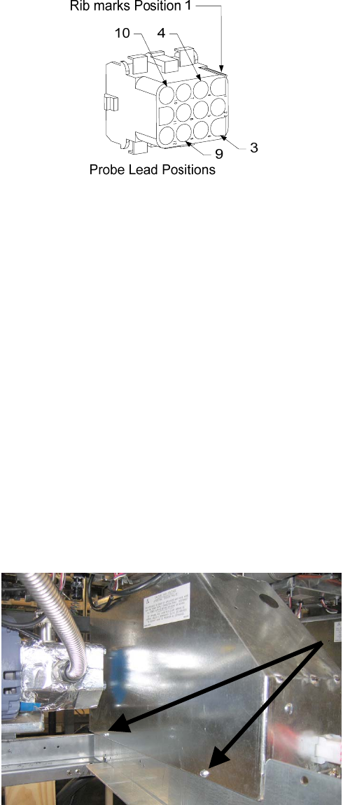
9. Insert the temperature probe leads into the 12-pin wiring harness connector (see illustration
below). For full-vat units or the right half of a dual-vat unit, the red lead goes into position 3 and
the white into position 4. For the left half of a dual-vat unit, the red lead goes into position 9 and
the white into position 10. NOTE: Right and left refer to the fryer as viewed from the rear.
10. Reconnect the 12-pin connector of the wiring harness disconnected in Step 2.
11. Lower the element to the full down position.
12. Reinstall the tilt housing, back panels and contactor plug guard. Reposition the fryer under the
exhaust hood, and reconnect it to the electrical power supply.
1.7 Replacing Contactor Box Components
1. If replacing a contactor box component in boxes above the filter pan, first remove the filter pan
and lid from the unit. If replacing components in fryers tht have ATO boxes, the ATO box may
require removal.
2. Disconnect the fryer from the electrical power supply.
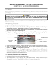
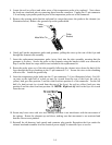
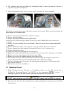
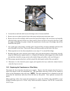
3. Remove the two screws securing the cover of the contactor box. The contactor boxes above the
filter pan are accessed by sliding under the fryer. They are located to the left and right above the
guide rails (see photo below). The contactor boxes for frypots not over the filter pan are accessed
by opening the fryer door directly under the affected frypot.
Remove two screws to access contactor box components above the filter
pan
.