


iv
BIELA14 SERIES GEN II LOV™
ELECTRIC FRYERS
TABLE OF CONTENTS
CAUTIONARY STATEMENTS ........................................................................................................................................ i
WARRANTY STATEMENT ............................................................................................................................................ ii
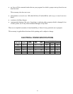
ELECTRICAL POWER SPECIFICATIONS ............................................................................................................... iii
CHAPTER 1: Service Procedures
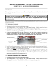
1.1 General ...........................................................................................................................................................1-1
1.2 Replacing a Computer ....................................................................................................................................1-1
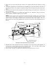
1.3 Replacing Component Box Components .......................................................................................................1-1
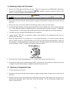
1.4 Replacing a High-Limit Thermostat ..............................................................................................................1-3
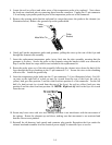
1.5 Replacing a Temperature Probe .....................................................................................................................1-3
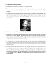
1.6 Replacing a Heating Element .........................................................................................................................1-5
1.7 Replacing Contactor Box Components ..........................................................................................................1-7
1.8 Replacing a Frypot .........................................................................................................................................1-8
1.9 Built-In Filtration System Service Procedures ............................................................................................. 1-10
1.9.1 Filtration System Problem Resolution........................................................................................ 1-10
1.9.2 Replacing the Filter Motor, Filter Pump and Related Components ........................................... 1-11
1.9.3 Replacing the Filter Transformer or Filter Relay ....................................................................... 1-13
1.10 ATO (Automatic Top-Off) Service Procedures ........................................................................................... 1-13
1.10.1 ATO Troubleshooting ................................................................................................................ 1-14
1.10.2 ATO Board Pin Positions and Harnesses ................................................................................... 1-15
1.10.3 Replacing the ATO board, LON Gateway, ATO pump relay or Transformer ........................... 1-16
1.10.4 Replacing the ATO Pump .......................................................................................................... 1-16
1.11 MIB (Manual Interface Board) Service Procedures ..................................................................................... 1-16
1.11.1 Manually Draining, Refilling or Filtering with the MIB Board ................................................. 1-17
1.11.2 MIB Troubleshooting ................................................................................................................. 1-18
1.11.3 MIB Pin Positions and Harnesses .............................................................................................. 1-20
1.11.4 MIB Display Diagnostics ........................................................................................................... 1-21
1.11.5 MIB Display Characters ............................................................................................................. 1-22
1.11.6 Replacing the MIB board ........................................................................................................... 1-22
1.11.7 Control Power Reset Switch....................................................................................................... 1-22
1.12 RTI Service Issues ....................................................................................................................................... 1-23
1.12.1 RTI MIB Tests .........................................................................................................
.................. 1-23
1.12.2 RTI LOV Wiring ........................................................................................................................ 1-24
1.12.3 RTI Plumbing Schematic ........................................................................................................... 1-24
1.12.4 RTI LOV Quick Reference ........................................................................................................ 1-25
1.13 AIF (Automatic Intermittent Filtration) Service Procedures ........................................................................ 1-27
1.13.1 AIF Troubleshooting .................................................................................................................. 1-27
1.13.2 AIF Actuator Board Pin Positions and Harnesses ...................................................................... 1-28
1.13.3 Replacing an AIF Board ............................................................................................................. 1-29
1.13.4 Replacing an Actuator ................................................................................................................ 1-29
1.14 M3000 Computer Service Procedures .......................................................................................................... 1-30
1.14.1 M3000 Computer Troubleshooting ............................................................................................ 1-30
1.14.2 M3000 Useful Codes and Passwords ......................................................................................... 1-33
1.14.3 Service Required Errors ............................................................................................................. 1-34
1.14.4 Error Log Codes ......................................................................................................................... 1-35
1.14.5 Tech Mode ................................................................................................................................. 1-36
1.14.6 M3000 Filter Error Flowchart .................................................................................................... 1-37
1.14.7 M3000 Menu Summary Tree ..................................................................................................... 1-38
1.14.8 M3000 Board Pin Positions and Harnesses ................................................................................ 1-39
1.15 Loading and Updating Software Procedures ................................................................................................ 1-40
1.16 Data Network Flowchart .............................................................................................................................. 1-41
1.17 Interface Board Diagnostic Chart ................................................................................................................. 1-42
1.18 Probe Resistance Chart ................................................................................................................................ 1-43
1.19 Wiring Diagrams .......................................................................................................................................... 1-44
1.19.1 Component Wiring Domestic .....................................................................................................1-44
1.19.2 Component Wiring CE ............................................................................................................... 1-45