


1-42
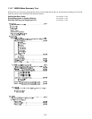
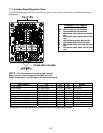
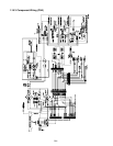
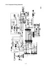
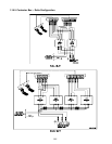
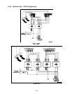
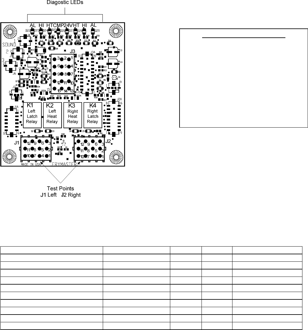
1.17 Interface Board Diagnostic Chart
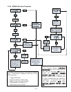
The following diagram and charts provide ten quick system checks that can be performed using only a
multimeter.
NOTE – Pin 1 is located in the bottom right corner of
Both J1 and J2. These test points are ONLY for LOV™
Series boards with J1 and J2 plugs on the front of the board.
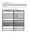
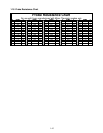
Meter Setting Test Pin Pin Results
12 VAC Power 50 VAC Scale 3 of J2 1 of J2 12-16 VAC
24 VAC Power 50 VAC Scale 2 of J2 Chassis 24-30 VAC
*Probe Resistance (RH) R X 1000 OHMS 11 of J2 10 of J2 See Chart
*Probe Resistance (LH) R X 1000 OHMS 1 of J1 2 of J1 See Chart
High-Limit Continuity (RH) R X 1 OHMS 9 of J2 6 of J2 0 - OHMS
High-Limit Continuity (LH) R X 1 OHMS 6 of J1 9 of J1 0 - OHMS
Latch Contactor Coil (RH) R X 1 OHMS 8 of J2 Chassis 3-10 OHMS
Latch Contactor Coil (LH) R X 1 OHMS 5 of J1 Chassis 3-10 OHMS
Heat Contactor Coil (RH) R X 1 OHMS 7 of J2 Chassis 11-15 OHMS
Heat Contactor Coil (LH) R X 1 OHMS 4 of J1 Chassis 11-15 OHMS
* Disconnect 15-Pin harness from the computer before testing the probe circuit.
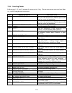
Diagnostic LED Legend
CMP indicates power from 12V transformer
24 indicates power from 24V transformer
HI (RH) indicates output (closed) from right latch
relay
HI (LH) indicates output (closed) from left latch
relay
HT (RH) indicates output from right heat relay
HT (LH) indicates output from left heat relay
AL (RH) indicates output (open) from right latch
relay
AL (LH) indicates output (open) from left latch
relay
PN 826-2260 (106-6664)