1-18
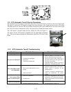
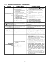
1.11.2 MIB (Manual Interface Board) Troubleshooting
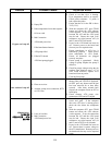
Problem Probable Causes Corrective Action
Auto filtration won’t
start.
A. Filter pan out of position.
B. Oil level too low.
C. Ensure MIB board is not in
manual mode.
D. Ensure MIB cover is not
damaged and pressing against
buttons.
E. Filter relay has failed.
F. AIF disable is set to YES, blue
light doesn’t light.
G. Filter motor thermal switch is
tripped.
H. AIF clock enabled
A. Ensure filter pan is fully inserted into fryer.
If the MIB board displays a “P” the pan is
not fully engaged into the pan switch.
B. Ensure the oil level is above the top oil
level sensor.
C. Ensure MIB board is in “A” automatic
mode.
D. Remove and replace cover and see if
filtration will start.
E. Replace filter relay with part number 807-
4482 24VDC relay.
F. Set AIF disable in Level 1 to NO.
G. Press filter motor thermal switch.
H. Ensure AIF clock is set to disabled.
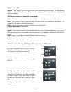
MIB display shows
something other than
an “A” or vat number.
An error has occurred and
displayed character indicates
error.
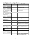
See MIB display diagnostics on page 1-21 for
explanation.
No power present at
the MIB board
Transformer has failed in left
component box.
Check output on the left transformer in left
component box; should read 24VAC. If not
replace transformer.
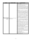
MIB will not clear
error.
Error remains in non-volatile
memory.
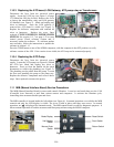
Press and hold reset button in top right corner
of MIB board for five seconds. The drain,
return and manual/auto LEDS will illuminate
and the MIB will reset and clear any remaining
errors from memory. Allow 60 seconds to reset.
If an error still exists, then another issue exists.
MIB indicates
incorrect number of
vats.
A. Network is not terminated
correctly.
B. Wiring harnesses are loose or
damaged.
C. An AIF board issue.
D. Locator pin issue.
A. Ensure the CAN bus system is terminated at
BOTH ENDS (on the M3000 connector J6
and on the ATO board connector J9) with a
resistor equipped 6-pin connector.
B. Unplug and reseat all wiring harnesses in
CAN system. Resistance between pins 2
and 3 on the CAN network connectors
should be 120 ohms.
C. Check software version numbers on all
M3000 computers and ensure all are display
an AIF version. If an AIF version is
missing, the AIF board may be missing
power or bad. Check pins 5 and on J4 and
J5 of the affected AIF board for proper
voltage.
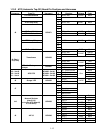
D. The locator pin in J2 of the AIF board is
either loose or in the incorrect position. See
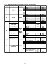
the charts on page 1-55 of this manual for
proper pin position.


