


1-2
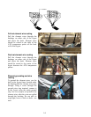
3. Remove the two screws from the upper corners of the computer and allow the computer to swing
down.
4. Unplug the wiring harnesses and disconnect the grounding wires from the terminals on the back of
the computer. Remove the computer assembly by lifting it from the hinge slots in the control panel
frame.
5. Disconnect the wiring from the component to be replaced, being sure to make a note of where each
wire was connected.
6. Dismount the component to be replaced and install the new component, being sure that any
required spacers, insulation, washers, etc. are in place.
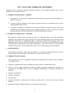
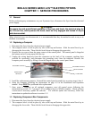
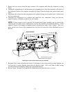
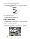
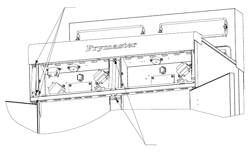
NOTE: If more room to work is required, the control panel frame assembly may be removed by
removing the hex-head screws which secure it to the fryer cabinet (see illustration below). If this
option is chosen, all computer assemblies must be removed per steps 1 thru 4 above. The cover
plate, on the lower front of the component box, may also be removed to allow additional access if
desired.
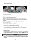
Remove these three
screws at each end.
Remove these two screws
from the center supports.
Removing the Control Panel Frame and Top Cap Assembly
7. Reconnect the wiring disconnected in step 5, referring to your notes and the wiring diagrams on
the fryer door to ensure that the connections are properly made. Also, verify that no other wiring
was disconnected accidentally during the replacement process.
8. Reverse steps 1 through 4 to complete the replacement and return the fryer to service.