


6-7
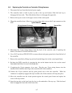
6.6 Replacing the Controller or Controller Wiring Harness
1. Disconnect the fryer from the electrical power supply.
2. The controller bezel is held in place by tabs at the top and bottom. Slide the bezel up to
disengage the lower tabs. Then slide the bezel down to disengage the upper tabs.
3. Remove the top two screws in the upper corners of the control panel.
4. Hinge the controller down. Allow it to rest on its hinge tabs to access the 15-pin connector on the
back.
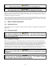
5. Disconnect the 15-pin wiring harness from the back of the controller and, if replacing the
harness, disconnect it from the interface board.
6. Use a 5/16” nut driver (P/N 802-0352) to remove the nut and green ground wire from the back of
the controller.
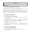
7. Remove the controller by lifting it up and out from the hinge slots in the control panel frame.
8. Re-hinge the NEW controller by inserting the tabs on the bottom into the slots on the control
frame panel and allow it to rest on the hinge tabs.
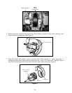
9. If replacing the 15-pin connector, do so now. Plug the new 15-pin wiring harness into the
interface board with the metal ring on the controller-end of the connector.
10. Connect the 15-pin connector and the green ground wire to the new controller. When the
connector is completely engaged, the clips on either side of the connector will snap into place.
11. Move the controller into the closed position against the control panel frame and replace the
screws in the top corners.
12. Insert the top tabs on the bezel into the slots on the underside of the top cap. Slide the bezel
down to engage the lower tabs in the lower slots.
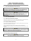
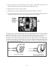
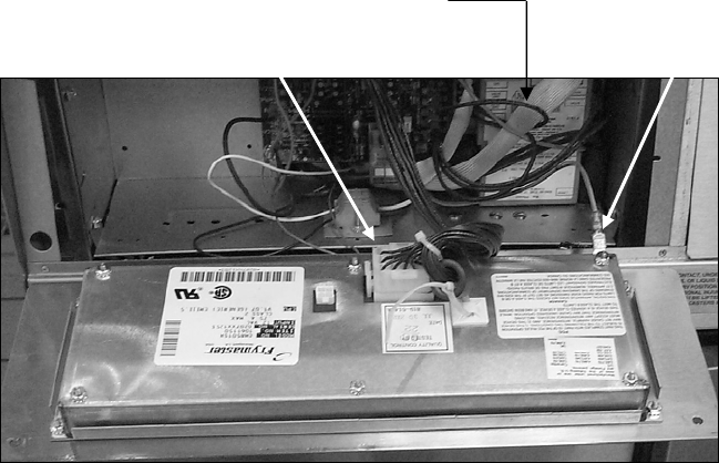
Ignition Module
Wiring Harness Connector
Ground Wire