


10.1.1 Wiring
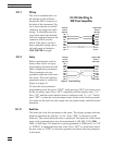
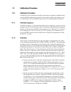
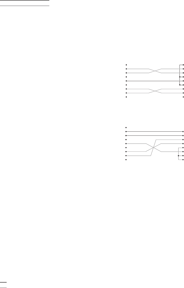
The serial communications ca
-
ble attaches to the calibrator
through the DB-9 connector at
the back of the instrument. Fig
-
ure 5 shows the pin-out of this
connector and suggested cable
wiring. To eliminate noise the
serial cable should be shielded
with low resistance between the
connector (DB-9) and the
shield. If the unit is used in a
heavy industrial setting, the se
-
rial cable must be limited to
ONE METER in length.
10.1.2 Setup
Before operation the serial in-
terface must first be set up by
programming the baud rate and
other configuration parameters.
These parameters are pro-
grammed within the serial inter-
face menu. The serial interface
parameters menu is outlined in
Figure 4 on page 36.
To enter the serial parameter
programming mode first press “EXIT” while pressing “SET” and release to en
-
ter the secondary menu. Press “SET” repeatedly until the display reads “PAr”.
Press “UP” until the serial interface menu is indicated with“SErIAL”. Finally
press “SET” to enter the serial parameter menu. In the serial interface parame
-
ters menu are the baud rate, the sample rate, the duplex mode, and the linefeed
parameter.
10.1.2.1 Baud Rate
The baud rate is the first parameter in the menu. The display prompts with the
baud rate parameter by showing “bAUd”. Press “SET” to choose to set the
baud rate. The current baud rate value is displayed. The baud rate of the instru
-
ment serial communications may be programmed to 300, 600, 1200, 2400,
4800, or 9600 baud. The baud rate is pre-programmed to 2400 baud. Use “UP”
or “DOWN” to change the baud rate value. Press “SET” to set the baud rate to
the new value or “EXIT” to abort the operation and skip to the next parameter
in the menu.
48
10 Digital Communication Interface
RS-232 Cable Wiring for
IBM PC and Compatibles
1NC
2 RxD
3 TxD
4NC
5 GND
6NC
7RTS
8 CTS
9NC
2 TxD
3 RxD
4RTS
5 CTS
6 DSR
7 GND
8 DCD
20 DTR
Instrument
Connector
(DB 9-Pin)
Computer (DTE)
Connector
(DB 25-Pin)
1NC
2 RxD
3 TxD
4NC
5 GND
6NC
7RTS
8 CTS
9NC
1 DCD
2 RxD
3 TxD
4 DTR
5 GND
6 DSR
7RTS
8 CTS
9NC
Instrument
Connector
(DB 9-Pin)
Computer (DTE)
Connector
(DB 9-Pin)
Figure 5 Serial Cable Wiring