


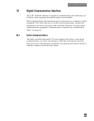
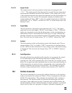
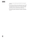
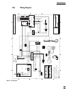
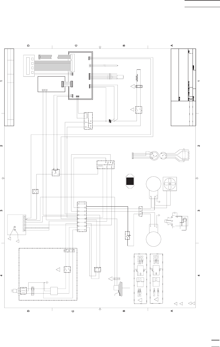
13.3 Wiring Diagram
59
13 Trouble Shooting
799 East Utah Valley Drive
American Fork, Utah 84003
(801) 763-1600
Probe
TC
Triac
AC
RED
RED
WHT
WHT
SHLD
+
-
H
N
MT2
G
MT1
J7
J8
J3
J9
J1
1
2
3
4
5
POWER
SUPPLY
Part #
90031021
4
2
8
6
0
1
G
MT2
MT1
Brn22
Gry22
Wht/Org/Blk 18
Vio 18
Wht/Org 18
Wht/Org/Blk 16
Wht/Org 16
SERIAL
INTERFACE
Heater
Fuses
Cut-Out
Relay
Wht16
Wht/Blk16
Wht/Red/Blk 16
Wht/Red 16
Gry 16
7
8
Wht/Yel/Blk 18
Blue 18
Brown 18
White 16
White/Blk 16
Brown 14
Blue 14
SYSTE
M
FUSES
AC
FILTER
POWE
R
SWITC
H
SECOND
S
TAGE
(LOW)
FIRST STAGE
(HIGH)
COOLING
ON
OFF
K3
K1
NOTES:
1- All wires shown are stranded copper with PVC
insulation rated at 105 C
u
nless otherwise specified.
2 Heater Fuses:
3 System Fuses:
Brown 14
Blue 14
Green/Yel 14
Ferrite
Wht/Yel/Blk 18
Wht/Yel 18
Vio 18
Wht/Yel18
Brown 14
Blue14
Wht/Vio/Blk 14
Wht/Vio 14
Wht/Blu/Blk 18
Wht/Blu 18
Wht/Vio/Blk 16
Wht/Vio 14
Wht/Vio/Blk 16
Vio 16
SECOND
S
TAGE
CUT-IN
7380 WIRING DIAGRAM
Joel Guzman 3/12/1999
1OF1
8
4
6
2
1
0
For 230 VAC
-
3 Amps 250 V FB.
COMPRESSOR
2
1
2
3
4
5
6
7
8
TB3
100 Ohm
RTD
P
robe
TypeK
Thermo-couple
Sensor
LID
4- All metal parts to be grounded.
T1
LTR
DESCRIPTION
BY
APPROVAL
DATE
REVISIONS
Blue 16
Brown 16
Vio 18
Vio 18
K2
Solid-State
Relay
For 230 VAC
-
10 Amps 250 V Slow
B
low.
For 115 VAC
-
6 Amps 250 V FB.
For 115 VAC
-
20 Amps 250 V Slow
B
low.
Vio22
Gry22
Blk22
Grn/Yel14
Grn/Yel14
STIR
M
OTOR
COOLING
J4
J1
J3
J1
J6
3
2
W4
W5
W6
W7
W8
W9
W13
W14
W15
W16
W19
W20
W26
W27
W23
W24
W25
W31
W32
W33
W34
W35
W36
W37
W18
W17
W40
W39
W38
W41
W28
W29
W42
W43
W51
W44
W45
W46
W47
W48
W49
W50
Gray 22
1
2
3N/C
3
2N/C
1
5
6
COMPRESSOR
1
Wht/Vio/Blk 16
Vio 16
Wht/Vio 16
Wht/Vio 16
Brown 14
Blue 14
Green/Yel 14
Brown 14
Blue 14
Green/Yel 14
W10
W11
W12
W1
W3
BACK PANEL
TB1
TB2
TB4
5
3
2
1
3
2
1
6
3
2
1
3
2
1
W21
W52
W53
J5
Yel 22
W54
Grn 22
W55
ANALOG PCB P/N
4
0004444 (TOP)
DIGITALPCB P/N
4
0001413 (BOTTOM)
Cutout
Relay
PANELPCB
P/N
4
0004443
1
2
0042-S060
AC
HI
AC
LO
Compressor's Internal
Conections
1- Red
2- Red
3- White
4- White
5- Shield
Probe
RTD
S
ensor
1
2
3
4
5
L2 230V
L2 115V
L1
COM
NO
NC
ICM 491
T1
MT1
MT2
G
Q4025P
+
-
10
11
12
13
14
7 Adjust input voltage to 115/230 VAC. Secure setting.
8 Set time delay to 2 minutes.
+
-
J10
+
-
Probe In-line
Connector
(Front View)
Probe Plug
(Front View)
1
2
3
4
1
2
3
4
SwitchCraft
In-line
Connector
Ground strap
from mounting
Plate to lid.
A
Added in-line probe connector
JG
ECO 7380-1
8/13/1999
A
Figure 6 Wiring Diagram