


10.1.2.2 Sample Period
The sample period is the next parameter in the menu and prompted with
“SPEr”. The sample period is the time period in seconds between temperature
measurements transmitted from the serial interface. If the sample rate is set to
5, the instrument transmits the current measurement over the serial interface ap
-
proximately every five seconds. The automatic sampling is disabled with a
sample period of 0. Press “SET” to choose to set the sample period. Adjust the
period with “UP” or “DOWN” and then use “SET” to set the sample rate to the
displayed value.
10.1.2.3 Duplex Mode
The next parameter is the duplex mode indicated with “dUPL”. The duplex
mode may be set to half duplex (“HALF”) or full duplex (“FULL”). With full
duplex any commands received by the thermometer via the serial interface are
immediately echoed or transmitted back to the device of origin. With half du
-
plex the commands are executed but not echoed. The default setting is half du
-
plex. The mode may be changed using “UP” or “DOWN” and pressing “SET”.
10.1.2.4 Linefeed
The final parameter in the serial interface menu is the linefeed mode. This pa-
rameter enables (“On”) or disables (“OFF”) transmission of a linefeed charac-
ter (LF, ASCII 10) after transmission of any carriage-return. The default setting
is linefeed off. The mode may be changed using “UP” or “DOWN” and press-
ing “SET”.
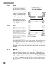
10.1.3 Serial Operation
Once the cable has been attached and the interface set up properly the control
-
ler will immediately begin transmitting temperature readings at the pro
-
grammed rate. The serial communications uses 8 data bits, one stop bit, and no
parity. The set-point and other commands may be sent via the serial interface to
set the temperature set-point and view or program the various parameters. The
interface commands are discussed in Section10.2. All commands are ASCII
character strings terminated with a carriage-return character (CR, ASCII 13).
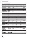
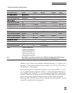
10.2 Interface Commands
The various commands for accessing the calibrator functions via the digital in
-
terfaces are listed in this section (see Table 3). These commands are used with
the RS-232 serial interface. The commands are terminated with a carriage-re
-
turn character. The interface makes no distinction between upper and lower
case letters, hence either may be used. Commands may be abbreviated to the
minimum number of letters which determines a unique command. A command
may be used to either set a parameter or display a parameter depending on
49
10 Digital Communication Interface