


16 Heat & Glo • VRTIKL-CE • 7031-292 Rev E • 12/07
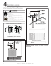
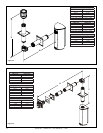
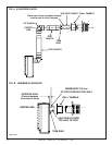
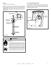
90 DEGREE
ELBOW
PIPE LENGTH
PIPE LENGTH
WALL THIMBLE
COVER
WALL THIMBLE
TERMINATION CAP
Step 1.
Determine the desired location of the gas stove. Check to
ensure that wall studs or roof rafters are not in the way when
the flue system is being planned. If this is the case, you may
want to adjust the location of the gas stove.
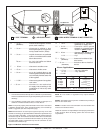
E. Horizontal Termination
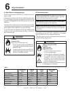
Step 3.
For installations using a round support box/wall thimble
(check pipe manufacturer's instructions), mark the wall for
a 25.4 cm x 25.4 cm square hole. The center of the square
hole should line up with the center line of the horizontal
pipe, as shown in Figure 5.12. Cut and frame the hole in
the exterior wall where the flue will be terminated. If the wall
being penetrated is constructed of noncombustible material,
i.e. masonry block or concrete, a 17.8 cm diameter hole is
acceptable.
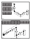
C
ENTER
LINE
CENTER LINE
6 in.
4 in.
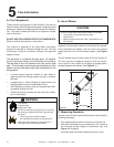
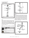
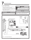
Step 2.
Balanced flue pipe is designed with a locking connection. To
connect the flue system to the gas stove flue outlet, a twist-
lock adapter is built into the gas stove at the factory. Wall
thickness may vary. Remember to include wall thickness in
minimum clearances when figuring flueing lengths for your
installation needs.
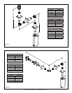
Female Locking Lugs
Male Locking Lugs
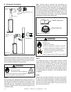
Fire Risk.
Explosion Risk.
Combustion Fume Risk.
Use fl ue run supports per installation instructions.
Connect fl ue sections per installation instructions.
• Maintain all clearances to combustibles.
• Do NOT allow fl ue to sag below connection
point to gas stove.
WARNING
Improper support may allow fl ue to sag or separate.
Fire Hazard.
Exhaust Fume Risk.
Impaired Performance of Appliance.
WARNING
• Ensure fl ue components are locked together correctly.
• Pipe may separate if not properly joined.
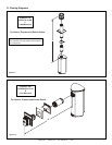
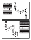
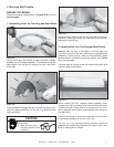
Step 4.
Position the horizontal termination cap in the center of the
25.4cm x 25.4cm square hole and run a bead of non-harden-
ing mastic around its outside edges, to make a seal between
it and the wall. Attach termination cap to the exterior wall
with the four wood screws provided. The arrow on the flue
cap should be pointing up.
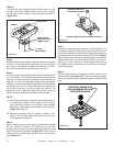
Note: Female ends of balanced flue pipe/elbows are
designed to slide straight onto the male ends of adjacent
pipes by orienting the pipe indentations so they match and
slide into the entry slots on the male ends, see Figure 5.13.
Push the pipe sections completely together, then twist-lock
one section clockwise approximately one-quarter turn, until
the two sections are fully locked. The female locking lugs
may not be visible from the outside. They may be located by
examining the inside of the female ends.
Figure 5.13
Figure 5.12