


17Heat & Glo • VRTIKL-CE • 7031-292 Rev E • 12/07
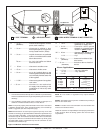
BEFORE YOU BEGIN:
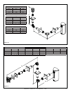
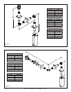
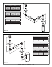
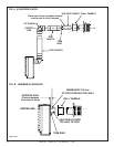
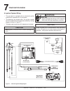
Review the fl ueing confi gurations in Figures A, B and C on
the next page.
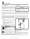
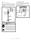
F. Slim Line Wall Thimble
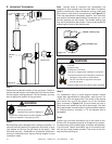
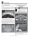
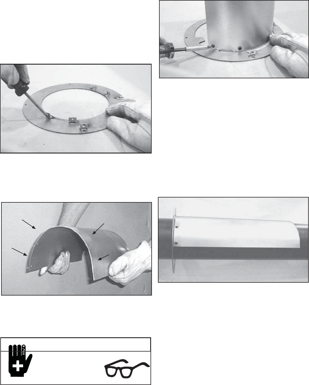
1. Assembling Slim Line Trim Ring and Heat Shield
2. Installing Slim Line Trim Ring and Heat Shield
Figure 5.14
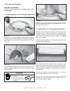
Lay the trim ring on fl at surface and bend up the six welded
brackets into a 90 degree position. The brackets along the
outer edge of the ring are for locating the ring in the center
of the hole.
Figure 5.15
The heat shield is shipped fl at and must be hand bent into a
half circle before attaching it to the trim ring. Bend the heat
shield as shown.
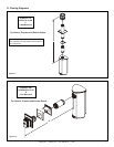
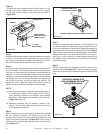
Figure 5.16
Attach the heat shield to the trim ring with the four screws
provided. Screws go through the heat shield and into the
brackets on the trim ring.
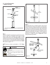
Figure 5.17
When installing the trim ring/heat shield assembly make
sure the trim ring is centered in the hole and that the shield
is above the pipe. There must be a minimum of 2 cm mini-
mum clearance maintained to combustibles from the top of
the heat shield.
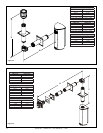
Measure from the fl oor to the center of the fl ue pipe. Cut
out a 25.4 cm hole in the wall. Hold the trim ring/heat shield
assembly in place and put a mark on the shield with a black
marker where it protrudes through the exterior wall. Figure
A on the next page.
Use that mark as a guide to trim off excess heat shield with
a pair of sheet metal shears.
Ensure that framing on the inside of the wall is a minimum
inner framing diameter of 25.4 cm x 25.4 cm.
The four trim ring mounting screws provided should be
replaced with appropriate fasteners for stucco, brick, con-
crete, or other types of sidings.
CAUTION
Sharp Edges
• Wear protective gloves
and safety glasses during
installation.