


9Heat & Glo • VRTIKL-CE • 7031-292 Rev E • 12/07
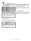
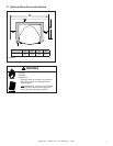
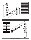
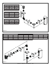
V
= VENT TERMINAL
X
= AIR SUPPLY INLET
= AREA WHERE TERMINAL IS NOT PERMITTED
Figure 4.4 Minimum Clearances for Termination
A = 31 cm ....................clearances above grade, veranda,
porch, deck or balcony
B = 31 cm ....................clearances to window or door
that may be opened, or to perma-
nently closed window. (Glass)
D* = 31 cm ....................vertical clearance to unventilated
soffi t or to ventilated soffi t located
above the terminal
76 cm .....................for vinyl clad soffi ts and below
electrical service
F = 23 cm ...................clearance to outside corner
G = 15 cm ....................clearance to inside corner
H = 91 cm ....................not to be installed above a gas
meter/regulator assembly within 90
cm horizontally from the center-line
of the regulator
I = 1.8 M .....................clearance to gas service regulator
vent outlet
J = 31 cm ......................clearance to non-mechanical
air supply inlet to building or the
combustion air inlet to any other
gas stove
K = 1.8 M .......................clearance to a mechanical
(powered) air supply inlet
L** = 2.1 M .......................clearance above paved
sidewalk or a paved driveway
located on public property
M*** = 46 cm ......................clearance under veranda, porch,
deck, balcony or overhang
1.1 M ......................vinyl
** a fl ue shall not terminate directly above a sidewalk or paved driveway
which is located between two single family dwellings and serves both
dwellings.
*** only permitted if veranda, porch, deck or balcony is fully open on a
minimum of 2 sides beneath the fl oor, or meets Note 2.
NOTE 1: On private property where termination is less than 7 feet above
a sidewalk, driveway, deck, porch, veranda or balcony, use of a listed cap
shield is suggested. (See fl ue components page)
NOTE 2: Termination in an alcove space (spaces open only on one side
and with an overhang) are permitted with the dimensions specifi ed for vinyl
or non-vinyl siding and soffi ts. 1. There must be 2.7M minimum between
termination caps. 2. All mechanical air intakes within 3M of a termination
cap must be a minimum of 2.7M below the termination cap. 3. All gravity
air intakes within 2.7M of a termination cap must be a minimum of .31M
foot below the termination cap.
(See Note 1)
(See Note 1)
(See Note 2)
NOTE 3: Local codes or regulations may require different
clearances.
NOTE 4: Termination caps may be hot. Consider their proximity to
doors or other traffi c areas.
NOTE 5: Location of the fl ue termination must not interfere with
access to the electrical service.
Heat & Glo assumes no responsibility for the improper performance
of the gas stove when the fl ueing system does not meet these
requirements.
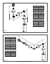
Q
MIN
= # termination caps x 3 R
MAX
= (2 / # termination caps) x Q
ACTUAL
Alcove Applications
S = 15 cm .......................clearance from sides of elec-
trical service
T = 31 cm ........................clearance above electrical
service
(See Note 5)
(See Note 5)
See Notes 3 & 4
Electrical
Service
V
S
V
S
V
T
D*
V
M
N
P
R
Q
Q
MIN
R
MAX
1 cap .91 M 2 x Q
ACTUAL
2 caps 1.8 M 1 x Q
ACTUAL
3 caps 2.7 M 2/3 x Q
ACTUAL
4 caps 3.7 M 1/2 x Q
ACTUAL
N = 15 cm .....................non-vinyl sidewalls
31 cm .....................vinyl sidewalls
P = 2.4 M