


25Heat & Glo • VRTIKL-CE • 7031-292 Rev E • 12/07
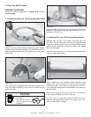
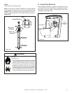
Figure 8.4
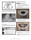
The manufacturer recommends securing the lag bolt from
the component bag in the center hole in the bottom plate
(clearance hole). This bolt will help to prevent tipping for-
ward.
CLEARANCE
HOLE
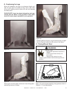
Figure 8.5
Using pliers, adjust the counter screws to level the gas
stove.
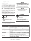
D. Accessories
Install approved accessories per instructions included with
accessories. Refer to Section 12F for appropriate acces-
sories.
Shock or fi re risk.
Use ONLY optional accessories approved for
this gas stove.
• Using non-listed accessories voids
warranty.
• Using non-listed accessories may result in a
safety hazard.
• Only Hearth & Home Technologies approved
accessories may be used safely.
WARNING
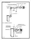
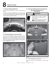
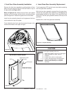
4. Remove the inner extension collar (Shown in Figure
8.7) and set aside.
5. Remove the four screws from the DV adapter collar
(Figure 8.7). Set aside DV adapter collar and
screws.
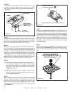
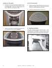
3. Remove and retain the Allen head screws that hold
the solid back panel in place (Figure 8.8). Remove
and discard the solid back panel.
Figure 8.7
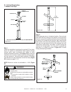
E. Top to Rear Flue Conversion
KIT CONTENTS: Top cover (without hole);
Back panel (with hole).
1. Remove the front door assembly by pulling bottom
of front away from gas stove and lifting it off of the
hooks on top of the gas stove. Set door aside.
ON TOP OF APPLIANCE:
2. Remove the top plate with hole and discard. (Figure 8.6)
Figure 8.6
I
I
NNER EXTENSION COLLAR
NNER EXTENSION COLLAR
DV ADAPTER
DV ADAPTER
ALLEN HEAD
ALLEN HEAD
SCREWS
SCREWS