


23Heat & Glo • VRTIKL-CE • 7031-292 Rev E • 12/07
7
Electrical Information
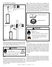
Battery polarity must be correct or module damage will
occur.
CAUTION
Label all wires prior to disconnection when servicing
controls. Wiring errors can cause improper and dangerous
operation. Verify proper operation after servicing.
CAUTION
Shock Risk
• Replace damaged wire with type 105° C rated wire.
• Wire must have high temperature insulation.
WARNING
BATTERY PORT
(4 AA BATTERIES)
VALVE
PILOT
IGNITION MODULE
6VDC
ON/OFF
SWITCH
THERMOCOUPLE
BLOCK
(CONNECTED TO
BACK OF VALVE)
PILOT GAS LINE
CONNECTED TO
BACK OF VALVE
IGNITION
MODULE
(6V)
ON/OFF
WALL SWITCH
VALVE
FLAME SPARKER/
SENSOR
ANT.
REMOTE
CONTROL
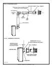
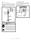
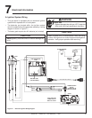
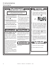
A. Ignition System Wiring
• This gas stove is equipped with an electronic ignition
system which operates on a 6 volt system.
• The batteries are located within the ignition module
which is located behind the glass door assembly. A wiring
diagram is shown in Figure 7.1.
• The battery pack requires four AA batteries (not included).
Figure 7.1 Electronic Ignition Wiring Diagram