


22 Heat & Glo • VRTIKL-CE • 7031-292 Rev E • 12/07
WARNING
WARNING
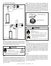
CHECK FOR GAS LEAKS
Fire Risk
Explosion Risk
Asphyxiation Risk
• Check all fi ttings and connections.
• Do not use open fl ame.
• After the gas line installation is complete,
all connections must be tightened and
checked for leaks with a commercially
available, non-corrosive leak check
solution. Be sure to rinse off all leak check
solution following testing.
Fittings and connections may have loosened
during shipping and handling.
Fire Risk
Explosion Risk
High pressure will damage valve.
• Disconnect gas supply piping BEFORE
pressure testing gas line at test pressures
above 60 mbar.
• Close the manual shutoff valve BEFORE
pressure testing gas line at test pressures
equal to or less than 60 mbar.
A. Gas Pressure Requirements
Pressure requirements for VRTIKL-CE Stoves are shown in
Table 1 below.
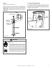
Two taps are provided on the right hand side of the gas control
for a test gauge connection to measure the inlet and outlet
pressures. See Section 10: Maintaining and Servicing the
Appliance.
The stove and its individual shut-off valve must be disconnected
from the gas supply piping system during any pressure testing
of the system at test pressures in excess of 60 mbar.
If the stove must be isolated from the gas supply piping
system by closing an individual shut-off valve, it must be of
the handle-less type.
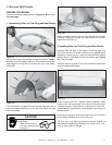
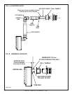
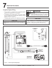
B. Gas Connection
Note: Have the gas supply line installed in accordance with
local building codes by a qualifi ed installer approved
and/or licensed as required by the locality.
Note: Before the fi rst fi ring of the stove, the gas supply
line should be purged of any trapped air.
Note: Consult local building regulations to properly size
the gas supply line leading to the (Rp 1/2 in.) hook-up
at the unit.
Incoming gas line should be piped into the valve compartment
and connected to the ISO 7-Rp 1/2 (BSP Rp 1/2 ) threaded
gas inlet connection on the manual shutoff valve.
Leak test all gas line points and the gas control valve prior to
and after starting the gas stove.
Table 1
6
Gas Information
Natural Gas
(G20)
Propane
(G31)
Butane
(G30)
Natural Gas
(G25)
Inlet Pressure 20mbar 37 or 50mbar 30 or 50mbar 25mbar
Manifold Pressure 4-8.4mbar 15.7-25mbar 15.7-25mbar 4-8.4mbar
Gas Rate .72
m
3
/
h
.26
m
3
/
h
.10
m
3
/
h
.67
m3
/
h
Max.Input (NETCV) 6.9 kW 6.6 kW 5.8 kW 5.5 kW
Burner Injector DMS 39 DMS 53 DMS 55 DMS 39
Pilot Injector 51 30 30 51