


– 6 –
UNPACKING
Immediately after unpacking the dishwasher, check for possible shipping damage.
If the machine is found to be damaged, save the packaging material and contact
the carrier within 15 days of delivery.
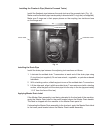
Before installation, test the electrical service to make sure it agrees with the
specicationsonthemachinedataplatelocatedonthecontrolbox.Theelectrical
diagram is located inside the control box.
Strainer baskets, strainer pans, pump inlet strainers and wash arms are taped
and shipped in place. Remove tape, but retain parts in their proper places. If any
parts are temporarily removed during installation, return to their proper places after
installation is complete.
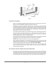
Before installing, check to make sure that necessary electrical, plumbing and exhaust
accommodations are provided at the installation location. Take measurements
of site’s plumbing, electrical and exhaust connections; then take corresponding
measurements of the machine to make sure all connections are correctly mated.
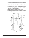
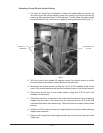
If necessary to lower control box during move-in, slotted holes are provided on the
control box shipping braces to allow adjustment for clearance height. Refer to page 4.
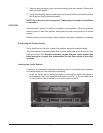
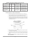
Removing Each Section From Its Skid
Do not use a forklift directly on the machine frame or tank to move
or lift machine sections. Doing so may result in damage to the machine.
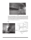
1. Using a forklift or pallet jack, raise one end of the skid and unthread the feet
from the legs as far as possible without removing the foot from the leg. Repeat
for other end until all feet have been extended out. Lower the skid back to the
oor.Thiswillnowallowthemachinetositonitsfeetsotheskidcaneasilybe
removed.
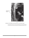
2. Remove the two end plate screws from the 2x4 runners, located just inside the
front and rear legs, at each end of the skid.
3. Remove all lag bolts from the top of the skid cross members along either the
front or rear of the machine.
4. From the opposite side of the machine that the lag bolts were removed in step
3, pull the entire skid assembly out from beneath the machine section.
5. Thread the feet into the legs as far as possible; then back out three full turns.
Standard legs have 3” threaded studs for maximum adjustment. If special feet
wereorderedwithextra-longlegshankstoaccommodateahighlyslopedoor,
installthemwherethelowpointsintheooroccuratleglocationsonthemachine
beforesettingtheunitontheoor.
6. Open all inspection doors and remove all wrapped parts and boxes from inside
each machine section.