


10
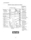
B. Sequence of Operation
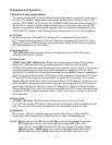
1. Sequence Cycles and Shutdown
The steps in the sequence are as outlined below. When power is supplied, power switch
is in the "ON" position, safety switch is engaged, and the control switch is in the "ICE"
position, CB"POWER" LED turns on. The "POWER" LED indicates control voltage and
will remain on unless a control voltage problem occurs. If icemaker does not start, BC
actuator and proximity switch may be engaged. Move the dispense mode switch to the
"CONTINUOUS" position, then dispense ice to lower the level of ice in the storage bin.
a) Fill Cycle
Reservoir is empty. LF/S and UF/S are open. WV energizes and ll cycle starts.
LF/Scloses. Nothing happens at this time. Reservoir continues to ll until UF/S closes.
When UF/S closes, WCR energizes, closing low water safety circuit and de-energizing
WV. GMenergizes once UF/S closes.
b) Ice Purge Cycle
"GM" LED is on. GM energizes. 60-sec. ice purge timer starts. Note: GM cannot
energize unless UF/S is closed.
c) Freeze Cycle
"COMP" and "GM" LEDs are on. 60-sec. ice purge timer terminates. GM continues.
CBconrms GM operation through GMPR terminal #3 (BR wire) and terminal
#5(DBUwire), then Comp and FM energize. Ice production starts 4to 6 min. after Comp
energizes depending on ambient and water temperature conditions. UF/S and LF/S
operate WV as needed to continue the icemaking process. Rell: As ice is produced the
water level in the reservoir drops. UF/S opens. Nothing happens at this time. LF/S opens.
FT starts. WCRde-energizes, energizing WV. As water lls the reservoir, LF/S closes.
Nothing happens at this time. Water continues to ll and UF/S closes. FT terminates and
WCRenergizes, closing low water safety circuit and de-energizing WV. If UF/S remains
open longer than 90 sec. after LF/S opens (FT exceeded), Comp and FM de-energize.
GM de-energizes 60 sec. later. WV remains energized until UF/S closes. The freeze cycle
continues until BC shuts the icemaker down, a drain cycle occurs, or power is turned off
to the icemaker.
d) Drain Cycle
"FLUSH" LED is on. The drain cycle occurs once every 12 hrs. for 20 min.
12-hr. DCT terminates, DVT starts. Comp and FM de-energize. GMde-energizes 60sec.
later. DVenergizes. DV remains energized for the remainder of the drain cycle.
e) Shutdown
BC activates, 150-sec. shutdown sequence starts. After 90 sec., Comp and FM
de-energize, AM energizes for 0.6 seconds, 60 sec. later, GM de-energizes.
Legend: AM–agitating motor; BC–bin control; CB–control board; Comp–compressor;
DCT–drain cycle timer (12-hr. timer); DV–drain valve; DVT–drain valve
timer(20-min. timer); FM–fan motor; FT–ll timer (90-sec. low water safety);
GM–gear motor; GMPR–gear motor protect relay; LF/S–loweroatswitch;
UF/S–upperoatswitch;WCR–water control relay; WV–inlet water valve