


29
•WaterDispenseSwitch/WaterDispenseSensor
a) Push Button Model: The water dispense button and DispWV are not associated with
CB. Engage the water dispense button, then check for 24VAC at DispWV. If 24VAC
is present and no water is dispensed, check for water supply line shut-off valve
closed, clogged water lters, clogged WV screen. If the water supply is good, replace
DispWV. If 24VAC is not present, check water dispense switch continuity and CT
24VAC fuse, 125VAC power supply, and continuity.
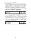
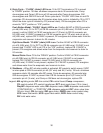
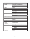
b) Opti-Serve Model: Before engaging the water dispense Opti-Serve sensor, check for
5VDC from the locations given in the table below. If VDC is different than in the table,
replace CB. If 5VDC is present, engage the Opti-Serve sensor and conrm that VDC
matches the table below. If not, see "IV.F.3c. Water Dispense" to rule out a faulty
Opti-Serve sensor. If the Opti-Serve sensor checks out, replace CB. If VDC matches
the table below when the Opti-Serve sensor is engaged, check for 24VAC between
CBK2connector pin #8 (DBU wire) to a neutral (LBU wire) with the Opti-Serve
sensor engaged. If 24VAC is not present, replace CB. If 24VAC is present and no
water is dispensed, check for water supply line shut-off valve closed, clogged water
lters, clogged WV screen. If the water supply is good, replace DispWV.
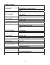
Control Board Connector To Control Board DC Ground Disengaged Engaged
K5 Pin #7 (R wire)
To K3 Pin #1 (open)
0VDC 0VDC
K5 Pin #8 (W wire) 5VDC 0VDC
K5 Pin #9 (BK wire) 5VDC 5VDC
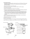
5) Fill Cycle – CB directs 24VAC power supply to WV from CB K2connector pin
#7(Rwire) to CB K3 connector pin #3 (DBU wire). Conrm 24VAC between
CBK2connector pin #7 (R wire) and pin #8 (LBU wire). Next, conrm 24VAC between
CB K3 connector pin #3 (DBU wire) and CB K2 connector pin #8 (LBU) wire. If 24VAC
is present between CB K2 connector pin #7 (R wire) and #8 (LBU wire), but not
between CB K3 connector pin #3 (DBU wire) and CB K2 connector pin #8 (LBU wire),
replace CB. If 24VAC is present between CB K3 connector pin #3 (DBU wire) and CB
K2connector pin #8 (LBU wire) and ll cycle does not start, see "IV.B.8) Fill Cycle."
6) Ice Purge Cycle – "GM" LED is on: UF/S closes, WCR relay terminal #6 (LBU
wire) and #4(Owire) close. CB K1 connector COM (BR wire) and CB K1 connector
NO(DBU wire) contacts close, energizing GM and GMPR. 60-sec. ice purge timer
starts. Check for 115VAC at CBK1 connector NO (DBU wire) to a neutral (W wire). If
115VAC is not present, conrm continuity between CB connector K4 pin #3 (GY wire)
and #4 (V wire). Next, conrm 115VAC at CB K1 connector COM(BR wire) to a neutral
(W wire). If 115VAC is present at CB K1 connector COM(BR wire) but not on NO (DBU
wire), and CB K4connector pin #3 (GY wire) and #4 (V wire) are closed, replace CB.
7) Freeze Cycle – "GM" and "COMP" LEDs are on: 60-sec. ice purge timer terminates.
CB X2 relay energizes, closing X2 relay contacts (BR and LBU wires). Conrm
continuity between CB K2 connector pin #1 (DBU wire) and #2 (BR wire). After being
closed for 60 seconds, conrm 115VAC between X2 (BR wire) and a neutral (Wwire).
Next, check for 115VAC between CB X2 (LBU wire) and a neutral (W wire). If 115VAC
is present on CB X2 (BR wire), but not on CB X2 (LBU wire) and CB K2 connector pin
#1(DBU wire) and #2 (BR wire) are closed, replace CB.