


34
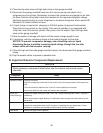
F. Diagnostic Charts
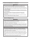
Before consulting the diagnostic charts, check for correct installation, proper voltage per
unit nameplate, and adequate water pressure (10 to 113 PSIG). Check CB using the steps
in "IV.C. Control Board Check."
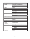
1. No Ice Production
Startup
1. Power Supply a) Off, blown fuse, or tripped breaker.
b) Not within specications.
2. Water Supply a) Water supply off or improper water pressure.
b) External water lters clogged.
3. Power Switch a) "OFF" position or defective.
4. Safety Switch a) Not engaged or defective.
5. Power Protect Relay a) Voltage not within specications.
b) Defective.
6. Control Transformer
(115VAC, 24VAC, and 10.5VAC)
a) Coil winding open or shorted.
7. 1A Fuse (24VAC Control Board) a) Blown.
8. .5A Fuse (10.5VAC Control
Board)
a) Blown.
9. Control Board
See "IV.C. Control Board Check"
a) Defective.
10. Control Switch a) In "OFF" or "DRAIN" position.
b) Defective.
11. Bin Control a) Tripped with bin lled with ice.
b) Proximity switch stuck open.
c) Actuator paddle does not move freely.
12. High-Pressure Switch a) Dirty condenser.
b) Ambient temperature too warm.
c) Fan motor not operating.
d) Refrigerant overcharged.
e) Bad contacts.
f) Refrigerant lines or components restricted.
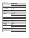
Fill Cycle
1. Water Control Relay a) Energized(upperoatswitchstuckclosed).
b) Defective.
2. Inlet Water Valve a) Screen or orice clogged.
b) Coil winding open.
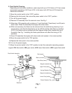
3. Float Switch
See "IV.E. Float Switch Check
and Cleaning"
a) Float does not move freely.
b) Defective.