


15
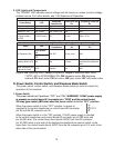
2. LED Lights and Components
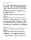
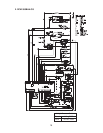
The "POWER" LED indicates control voltage and will remain on unless a control voltage
problem occurs. For further details, see "II.B. Sequence of Operation."
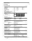
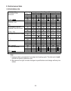
Icemaking
Cycle (Relay) LED
Energized
Components
Time LEDs are
On
Frequency LEDs are
On
Fill - WV N/A N/A
Ice Purge (X1) GM GM 60 sec. N/A
Freeze (X1, X2) GM, COMP GM, Comp, FM N/A N/A
Drain
(X5 push button)
(X6 OS)
FLUSH (drain) DV 20 min. Every 12 hr.
Ice/Water Dispense
Relay LED
Energized
Component
Time LEDs are
On
Frequency LEDs are
On
Ice Dispense (X4)
Push Button
DM
DM, DS 60 sec. max. N/A
Opti-Serve
ICE
Agitating Motor (X3) AM AM 0.6 sec.
Every 12 sec. of
accumulative dispense
time
Water Dispense (X5)
(Opti-Serve Only)
WTR DispWV N/A N/A
Legend: AM–agitating motor; Comp–compressor; DispWV–dispense water valve
("WTR" LED on DCM-300BAH-OS); DM–dispense motor; DS–dispense
solenoid; DV–drain valve; FM–fan motor; GM–gear motor; WV–inlet water valve
D. Power Switch, Control Switch, and Dispense Mode Switch
The power switch, control switch, and dispense mode switch are used to control the
operation of this icemaker.
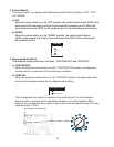
1. Power Switch
The power switch has 2 positions, "OFF" and "ON." WARNING! 115VAC power supply
is present on control board K1 connector pin "COM" and the control board
X2relay (gear motor) (BR wire) when the power switch is in the "OFF" position.
When the power switch is in the "OFF" position, no power is
supplied to the control transformer or control board K2connector
pin #3 and the K2 connector pin#5.
When the power switch is in the "ON" position, 115VAC power supply is directed
to the control transformer and control board K2 connector pin #3 (BK wire) and
pin #5(BKwire). The control board then directs 24VAC from the K3 connector
pin#3(DBUwire) to one side of the double-pole double-throw control switch, at the
same time, the control board directs 5VDC from the K4connector pin #4 (V wire) to the
other side of the control switch.