


28
b) Opti-Serve Model – "ICE" and "AM" LEDs are on:
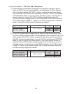
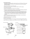
(1) "CONTINUOUS" Mode: Before engaging the ice dispense Opti-Serve sensor,
check for 5VDC from the locations given in the table below. If VDC is different
than in the table, replace CB. If VDC is correct, engage the Opti-Serve sensor
and conrm that VDC matches the table below. If not, see "IV.F.3a. Ice Dispense
"CONTINUOUS" Mode" to rule out a faulty Opti-Serve sensor. If the Opti-Serve
sensor checks out, replace CB. If VDC matches the table below when the
Opti-Serve sensor is engaged and ice is not dispensed, check CB K2 connector
pin #6 (LBU wire) for 115VAC. If 115VAC is not present, replace CB. If 115VAC is
present, check DS and DM continuity. Replace as needed.
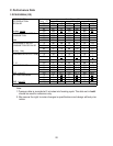
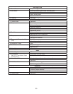
Control Board Connector To Control Board DC Ground Disengaged Engaged
K5 Pin #4 (W/O wire)
To K3 Pin #1 (open)
0VDC 0VDC
K5 Pin #5 (Y wire) 5VDC 0VDC
K5 Pin #6 (W/BR wire) 5VDC 5VDC
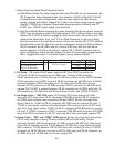
(2) "PORTION" Mode: Before engaging the ice dispense Opti-Serve sensor, check
for 5VDC from the locations given in the table below. If VDC is different than in the
table, replace CB. If VDC is correct, engage the Opti-Serve sensor and conrm
that VDC matches the table below. If not, see "IV.F.3b. Ice Dispense "PORTION"
Mode" to rule out a faulty Opti-Serve sensor. If Opti-Serve sensor checks out,
replace CB. If the VDC matches the table below when the Opti-Serve sensor is
engaged and ice is not dispensed, check CB K2 connector pin #6 (LBUwire) for
115VAC. If 115VAC is not present, replace CB. If 115VAC is present, check DS
and DM continuity. Replace as needed.
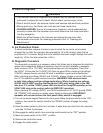
Control Board Connector To Control Board DC Ground Disengaged Engaged
K5 Pin #1 (W/R wire)
To K3 Pin #1 (open)
0VDC 0VDC
K5 Pin #2 (W/BU wire) 5VDC 0VDC
K5 Pin #3 (W/BK wire) 5VDC 5VDC