


13
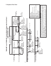
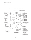
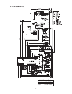
• "POWER" LED (green)
(lights when 10.5VAC is
supplied to K4 connector
pins #1 & #2)
• "FLUSH" (drain) LED
(X5 Relay)
K2 Connector Pin #8
12-hr. Drain Timer
K3 Connector Pin #3
Control Switch
"DRAIN" Position
• "COMP" LED (X2 Relay)
X2 Relay Terminals (115VAC)
• "GM" LED (X1 Relay)
K1 Connector Pin "NO"
• "DM" LED (X4 Relay)
K2 Connector Pin #6
•K3 Connector
#3 24VAC Output to
Control Switch,
Inlet Water Valve,
Water Control Relay,
and Drain Valve
• Ice Dispense Time Control
• "AM" LED (X3 Relay)
K2 Connector Pin #4
• Counter Reset Button
(not used in this application)
Control Board
Part Number 2A1592-01
1. Control Board Layout
a) DCM-300BAH
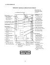
• "FLUSH" (drain) Switch
(Do not adjust)
• K2 Connector
#1, 2 Gear Motor
Protect Relay Circuit
(5VDC)
#3 Power Supply Input
(115VAC)
#4 "AM" LED: Agitating Motor
(115VAC)
#5 Power Supply Input
(115VAC)
#6 "DM" LED: Ice Dispense
Solenoid and Motor
(115VAC)
#7 Control Transformer
(24VAC)
#8 "FLUSH" (drain) LED:
Drain Valve (After 12-hr.
timer terminates) (24VAC)
•K1 Connector
"COM" Power Supply Input
(115VAC)
"NO" "GM" LED: Gear Motor
and Gear Motor
Protect Relay
• K4 Connector
#1, 2 Control Transformer
(10.5VAC)
#3, 4 Bin Control,
Control Switch "ICE",
and Water Control
Relay Circuit (5VDC)
#5 Ice Dispense Continuous
Operation (5VDC)
#6, 8 Ice Dispense Switch
and Dispense Mode
Switch (5VDC)
#7 Ice Dispense Portion
Operation (5VDC)
#9, 10, High-Pressure Switch
(5VDC)
"DCM-PB" Push Button Model Control Board
• Relay LEDs (red)
(indicate which relays
and connector pins are
energized)