


26
C. Control Board Check
Before replacing CB that does not show a visible defect and that you suspect is bad,
conduct the following CB check. This procedure will help you verify your diagnosis.
Before proceeding, check for proper voltage per unit nameplate. Check that the 24VAC
1A fuse, 10.5VAC 0.5A CT fuse are good, and the 115VAC GM external protector is not
tripped. When checking high-voltage (115VAC), always choose a neutral (W wire) to
establish a good neutral connection. When checking low-voltage (24VAC and 10.5VAC),
always choose a neutral (LBU wire) from CT to establish a good neutral connection.
WARNING! LBU wires are used in both high-voltage and low-voltage applications.
When checking low-voltage (24VAC and 10.5VAC) conrm that the neutral (LBU
wire) being used is the CB K4 connector pin #2 (LBU wire) from the CT. Not the
LBU wire used for GM operation (115VAC) or DV (24VAC power supply) operation.
When checking CB DC-voltage (5VDC), use CB K3 connector pin #1 for DC ground
(GND). The "POWER" LED remains on unless power supply is interrupted.
IMPORTANT! Icemaker will not start unless the front panel safety switch is
engaged.
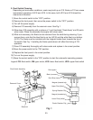
1) Remove the front panel and control box cover.
2) Turn on the power supply. Move the power switch to the "ON" position.
3) Startup – "POWER" LED on: Move the control switch to the "ICE" position. Engage the
safety switch, the "POWER" LED turns on. IMPORTANT! CB "POWER" LED will not
come on unless the front panel safety switch is engaged. Diagnosis: If "POWER"
LED does not turn on, check for 10.5VAC at CBK4 connector pin #1 (BR wire) to
pin #2(LBU wire). If 10.5VAC is present, and the "POWER" LED is off, replace CB. If
10.5VAC is not present, see "IV.B.7) Startup."
4) 5VDC Output Checks:
There are 6 CB circuits utilizing 5VDC: high-pressure switch, icemaking control circuit,
freeze protect circuit, ice dispense switch, dispense mode switch ("CONTINUOUS" or
"PORTION"), and the water dispense switch/water dispense sensor (Opti-Serve model
only). The high-pressure switch and the icemaking control circuit can prevent CB from
starting the icemaking process.
•High-PressureSwitch:CBmusthavecontinuitythroughHPStostarttheicemaking
process. HPS is a normally closed switch. Before proceeding to CB check, conrm
HPS condition. Turn off the power supply, then remove HPS wires and check continuity
across HPS. If open, allow to reset. If HPS does not reset, see "IV.B.10) Freeze Cycle."
a) Push Button Model: If HPS closed, check for 5VDC from CB K4 connector pin
#10(Vwire) to CB K3 connector pin #1 (open). If 5VDC is not present and "POWER"
LED is on, replace CB. If 5VDC is present, check for 5VDC from CB K4 connector
pin #9 (BR wire) to CB K3 connector pin #1 (open). If 5VDC is not present, replace
HPS or HPS wiring. If 5VDC is present, HPS circuit is good and WV should energize
and start lling the reservoir. If not, see "IV.C.5) Fill Cycle."
b) Opti-Serve Model: If HPS closed, check for 5VDC from CB K4 connector pin
#6(BRwire) to CB K3 connector pin #1 (open). If 5VDC is not present and
"POWER" LED is on, replace CB. If 5VDC is present, check for 5VDC from CB
K4connector pin #5 (V wire) to CB K3 connector pin #1 (open). If 5VDC is not
present, replace HPS or HPS wiring. If 5VDC is present, HPS circuit is good and WV
should energize and start lling the reservoir. If not, see "IV.C.5) Fill Cycle."