


R
mPGA604 Socket Design Guidelines 11
2 Assembled Component and
Package Description
Information provided in this section is to ensure dimensional compatibility of the mPGA604 socket
with that of the 604-pin processor package. The processor package must be inserted into the
mPGA604 socket with zero insertion force when the socket is not actuated.
2.1 Assembled Component Description
The assembled component may consist of a heatsink, EMI shield, clips, fan, retention mechanism
(RM), and processor package. Specific details can be obtained from Thermal Design Guidelines,
consult your Intel field representative to obtain this document.
2.2 Package Description
The outline of the processor package that can be used with the mPGA604 socket is illustrated in
Figure A-1. This drawing does not include potential heatsinks since these are used at the OEM's
discretion.
The pin-out for the 604-pin processor package is shown in Figure A-2.
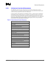
The pin dimension details, base material, plating material and plating thickness are shown in
Figure A-3. Note the dimensional variation when designing to ensure ZIF. The package Critical-To-
Function (CTF) dimensions are presented in Table 2-1. CTF values are detailed on the processor
package drawings and take precedence over all values presented in this document.
Table 2-1. Package Critical-To-Function (CTF) Dimensions
Dimension
Shoulder Diameter (Land Solder Fillet Shoulder Inclusion)
Pin Diameter
Shoulder Diameter Protrusion (Land Solder Fillet Shoulder
Inclusion)
Pin Length (Effective)*
Pin True Position (Pattern Relating and Feature Relating)*
Flatness of Processor*
Note: Pin length, pin true position and flatness tolerances are controlled by Geometric Dimensioning and
Tolerancing (GD&T) controls.