


R
mPGA604 Socket Design Guidelines 19
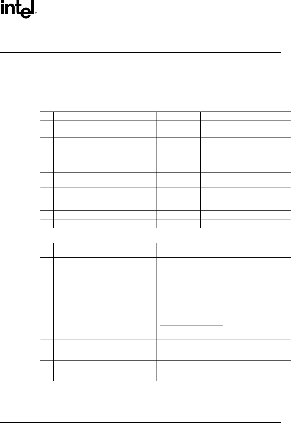
4 Electrical Requirements
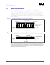
Socket electrical requirements are measured from the socket-seating plane of the processor test
vehicle (PTV) to the component side of the socket PCB to which it is attached. All specifications are
maximum values (unless otherwise stated) for a single socket pin, but includes effects of adjacent
pins where indicated. Pin and socket inductance includes exposed pin from mated contact to bottom
of the processor pin field.
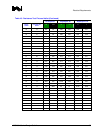
Table 4-1. Electrical Requirements for Sockets
1 Mat11 loop inductance, Lloop <4.33nH Refer to Table 4-2, Item 1
2 Mated partial mutual inductance, L NA Refer to Table 4-2, Item 2a
3 Maximum mutual capacitance, C <1pF Refer to Table 4-2, Item 3
4 Maximum Ave Contact Resistance ≤ 17mΩ Refer to Table 4-2, Item 4
Refer to Section 4.1 for more detail.
Refer to mPGA603 Socket Design
Guidelines for electrical parameters
with INT3 packages.
5
Measurement frequency(s) for Pin-to-
Pin/Connector-to-Connector capacitance.
400 MHz
6
Measurement frequency(s) for Pin-to-
Pin/Connector-to-Connector inductance.
1 GHz
7 Dielectric Withstand Voltage 360 Volts RMS
8 Insulation Resistance 800 M Ohms
9 Contact Current Rating Read and record
Table 4-2. Definitions
1
Mated loop inductance, Lloop
Refer to Table 4-1, Item 11
The inductance calculated for two conductors, considering
one forward conductor and one return conductor.
2a
Mated mutual inductance, L
Refer to Table 4-1, Item 2
The inductance on a conductor due to any single
neighboring conductor.
3
Maximum mutual capacitance, C
Refer to Table 4-1, Item 3
The capacitance between two pins/connectors.
4
Maximum Average Contact Resistance
Refer to Table 4-1, Item 4
The max average resistance target is originally derived from
max resistance of each chain minus resistance of shorting
bars divided by number of pins in the daisy chain.
This value has to be satisfied at all time. Thus, this is the
spec valid at End of Line, End of Life and etc.
Socket Contact Resistance:
The resistance of the socket
contact, interface resistance to the pin, and the entire pin to
the point where the pin enters the interposer; gaps included.
5 Measurement frequency(s) for Capacitance
Capacitively dominate region. This is usually the lowest
measurable frequency. This should be determined from the
measurements done for the feasibility.
6 Measurement frequency(s) for Inductance
Linear region. This is usually found at higher frequency
ranges. This should be determined from the measurements
done for the feasibility.