


R
Mechanical Requirements
mPGA604 Socket Design Guidelines 15
3.6 Socket Size
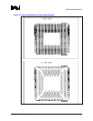
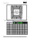
The socket size must meet the dimensions as shown in Figure A-5 and Figure A-6, allowing full
insertion of the pins in the socket, without interference between the socket and the pin field. The
mPGA604 socket and actuation area must fit within the keep-in zone defined in Figure A-6.
3.7 Socket/Package Translation During Actuation
The socket shall be built so that the post-actuated package pin field displacement will not exceed
1.27 mm. Movement will be along the Y direction (refer to axes as indicated in Figure A-5. No Z-
axis travel (lift out) of the package is allowed during actuation.
3.8 Orientation in Packaging, Shipping and Handling
Packaging media needs to support high volume manufacturing.
3.9 Contact Characteristics
3.9.1 Number of Contacts
Total number of contacts: 603.
Total number of contact holes: 604.
3.9.2 Base Material
High strength copper alloy.
3.9.3 Contact Area Plating
0.762 µm (min) gold plating over 1.27 µm (min) nickel underplate in critical contact areas (area on
socket contacts where processor pins will mate) is required. No contamination by solder in the
contact area is allowed during solder reflow.
3.9.4 Solder Ball Attachment Area Plating
3.81 µm (min) Tin/Lead (typically 85±5Sn/15Pb).
3.9.5 Solder Ball Characteristics
Tin/Lead (63/37 ± 0.5% Sn).